Magnamont™
The Industrial Standard for Liquid Level Monitoring
Versatile, maintenance-free level measurement tailored to your specific pressure and temperature requirements.
Magnamont™ magnetic level gauges are engineered for industrial process applications requiring robust construction and mechanical dependability. Utilizing a proven external chamber design, Magnamont delivers continuous level indication while isolating the indicator from direct contact with the process media.
Designed as a safer alternative to traditional glass level gauges, Magnamont reduces maintenance risks and eliminates leak paths while maintaining clear visibility. The platform supports customizable chamber configurations and material options, allowing it to be tailored to a wide variety of vessels and installation requirements.
With construction available to ASME B31.1 and B31.3 standards, Magnamont is the versatile solution for utilities, manufacturing, and general process industries where consistent, non-invasive level measurement is required.
Specifications at a Glance
Construction: Engineered alloys including SS304, SS316, Hastelloy, and Monel.
Pressure Rating: Full vacuum to 250 bar (3,625 psig).
Operating Temperature: Reliable performance from -200°C to +450°C (-328°F to +842°F).
Specific Gravity: Capable of measuring fluids with SG as low as 0.34.
Compliance: Engineered to ASME B31.1 / B31.3 and CSA W47.1 standards.
Measuring Length: Standard ranges up to 40 ft (12.2 m) with extended lengths available.
Indication: High-visibility magnetic flags with optional transmitter and switch integration.
Magnamont: The Robust Standard for Industrial Level Control
A robust magnetic level solution engineered for demanding process conditions with full compatibility for LevelSync™ automation and SurePoint™ level switches.
Industrial Integrity: Rugged Construction Standards
In power generation and petrochemical sectors, lightweight level gauges often fail to meet the structural rigor of process piping systems.
The Magnamont Edge: Magnamont is built using heavy-duty schedule pipe and industrial-grade welding standards (CSA W47.1). For critical applications, we offer construction options fully compliant with ASME B31.1 and B31.3 piping codes to match your vessel specifications.
Engineering Impact: This allows you to specify instrumentation that meets the same safety factors and mechanical strength standards as your process piping, ensuring regulatory compliance where it matters most without over-engineering standard units.
Seamless Automation: LevelSync™ & SurePoint™ Integration
Upgrading to a magnetic gauge offers more than just visual indication; it turns a mechanical vessel into a smart monitoring point.
The Magnamont Edge: The Magnamont chamber is designed for the easy integration of LevelSync™ transmitters and SurePoint™ switches. These accessories are externally clamped and magnetically actuated by the internal float, allowing for signal integration without additional vessel penetrations.
Engineering Impact: You achieve continuous 4-20 mA level measurement and point-level alarming while maintaining a fully sealed pressure boundary. Installation and calibration can be performed while the vessel is live, avoiding costly process shutdowns.
High-Visibility Monitoring: Clear Visual Verification
Traditional glass sight gauges are notorious for fouling, fogging, or becoming opaque over time due to process coating or condensation.
The Magnamont Edge: Because the indicator is mounted externally and magnetically coupled to the float, it never touches the process media. High-contrast flags provide a clear, bright level indication that remains readable from a distance.
Engineering Impact: This provides a permanent, maintenance-free visual reference that cannot cloud or stain, ensuring operators can verify levels instantly without approaching hot or hazardous equipment.
Shatter-Proof Safety: Redefining the Pressure Boundary
Standard reflex and transparent glass gauges rely on long, compressive sealing surfaces between the glass, gasket, and metal body. Under thermal cycling or vibration, these are frequent failure points that lead to hazardous leaks.
The Magnamont Edge: Magnamont replaces the fragile glass assembly with a welded, all-metal bypass chamber. While standard process connections are retained, the continuous vertical leak paths associated with viewing glass are completely eliminated.
Engineering Impact: This design isolates the process liquid within a pressure-rated pipe column, removing the risk of glass blowout and gasket fatigue, significantly enhancing personnel safety in high-temperature applications.
Engineered for Everyday Industrial Reliability
From storage tanks to utility skids, Magnamont delivers versatile, maintenance-free level monitoring across your entire facility.
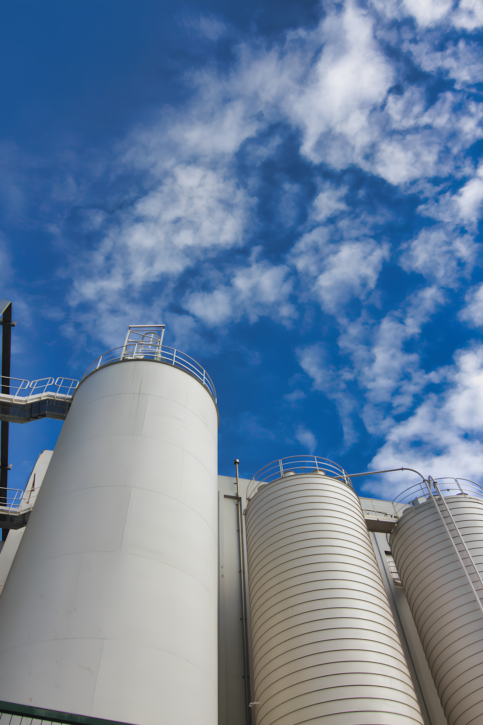
Magnamont is the universal standard for day tanks, mixing vessels, and batch reactors across general manufacturing industries. Whether handling solvents, process water, or raw materials, its rugged alloy construction replaces fragile sight glasses with a durable, maintenance-free solution. The flexible side, top, or bottom connection options allow it to retrofit easily onto existing vessels, providing safer containment and clear visibility for operators on the plant floor.
General Process & Storage Tanks

Plant Utilities & Steam Services
Reliable level control is critical for the auxiliary systems that keep your plant running, including condensate receivers, feedwater tanks, and hotwells. Magnamont withstands the thermal cycling and vibration inherent in steam and water loops without the risk of leaks common to gasketed glass gauges. With ASME B31.1 construction options available, it provides a robust, long-life solution for your facility’s critical utility infrastructure.
Chemical Distillation & Recovery
The welded chamber design ensures total containment of volatile organic compounds, eliminating fugitive emissions in solvent recovery units.
OEM Equipment Skids
A premium, customizable gauge solution that matches the quality and lifespan of high-value compressor packages and industrial boilers.
Water & Wastewater Treatment
Provides robust pressure containment for filtration skids and surge tanks where standard plastic gauges lack necessary structural integrity.
Fuel & Lubrication Systems
Ideal for diesel storage and hydraulic skids, featuring shock-resistant construction that withstands heavy machinery vibration without cracking.
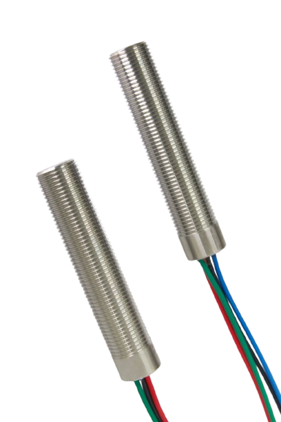
Automation & Integration
Continuous Monitoring and Point-Level Control
Polysight magnetic level gauges support external automation and alarm functions through non-invasive integration with LevelSync™ magnetostrictive transmitters and SurePoint™ level switches. These accessories are externally mounted and magnetically actuated by the internal float, enabling signal integration without introducing additional wetted process connections or vessel penetrations.
Because transmitters and switches are non-wetted, they can be installed, adjusted, or serviced without opening the vessel, depressurizing the system, or interrupting operation. This preserves the integrity of the chamber while supporting modern control and monitoring requirements.
LevelSync™
Continuous Level Transmitters
LevelSync magnetostrictive transmitters provide continuous level measurement by sensing the position of the magnetic float through the chamber wall. The transmitter mounts externally to the gauge and provides a standard 4 to 20 mA output, with optional digital communication depending on configuration.
As a non-wetted device, the transmitter remains isolated from corrosive process media and can be installed or serviced independently of the gauge chamber.
SurePoint level switches provide discrete high or low level indication for alarms and basic control functions. Switches are externally mounted and magnetically actuated as the float passes the setpoint location.
Setpoints may be adjusted along the chamber without process interruption, allowing flexible configuration during commissioning or future system changes.
Point Level Switches
SurePoint™
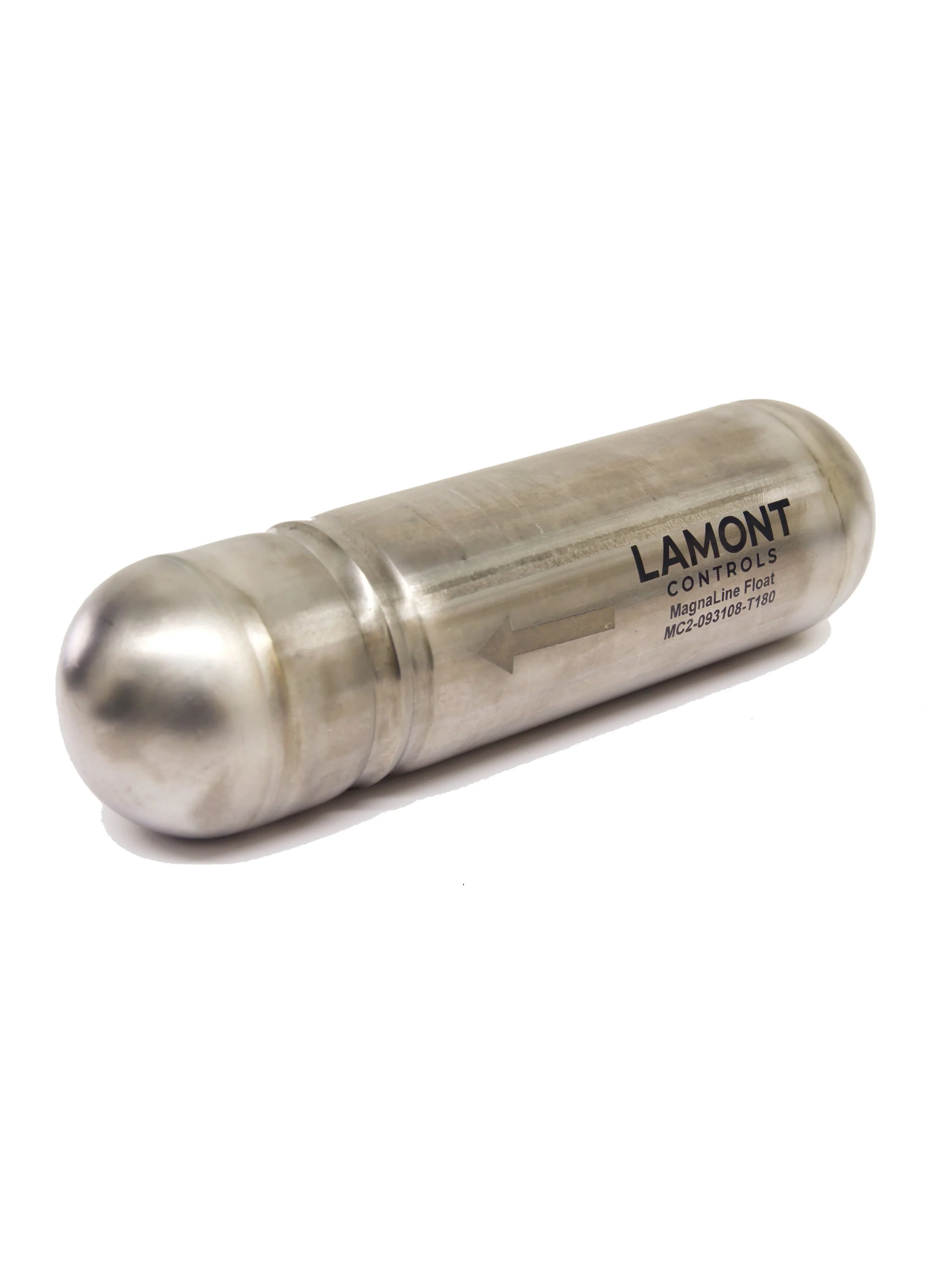
MagnaLine™ Float Technology
At the core of the gauge is the MagnaLine™ float. Engineered for stability, each float utilizes a high-strength, 360-degree magnetic flux assembly designed to maximize coupling force with the external indicator. This design ensures robust signal retention during standard operation and minimizes the risk of decoupling during process fluctuations.
Because accuracy depends on physics, every MagnaLine float is precision-weighted to the exact Specific Gravity (SG) and operating pressure of your fluid. Whether utilizing Titanium for high-pressure service or Stainless Steel for standard applications, we engineer the float to maintain the correct buoyancy relative to the fluid density, ensuring the indicated level matches the true process level.
Optional FloatSense™ Technology
Real-Time Float Integrity Monitoring
Eliminate the "blind spot" in level measurement. FloatSense™ provides early detection of float anomalies. In critical applications, this diagnostic feature warns operators if a float has been compromised or is failing to track, allowing for proactive maintenance before a process upset occurs.
-
![]()
Solid Thermoplastic MagnaLine Float
Constructed from solid PVDF, PVC, or PP to provide impervious resistance to aggressive acids and caustics.
-
![]()
Syntactic Foam MagnaLine Float
Syntactic foam float for ultra-high-pressure process applications.
-
![]()
PTFE (Teflon®) Coated MagnaLine Float
PTFE-coated float for highly corrosive chemical service.
-
![]()
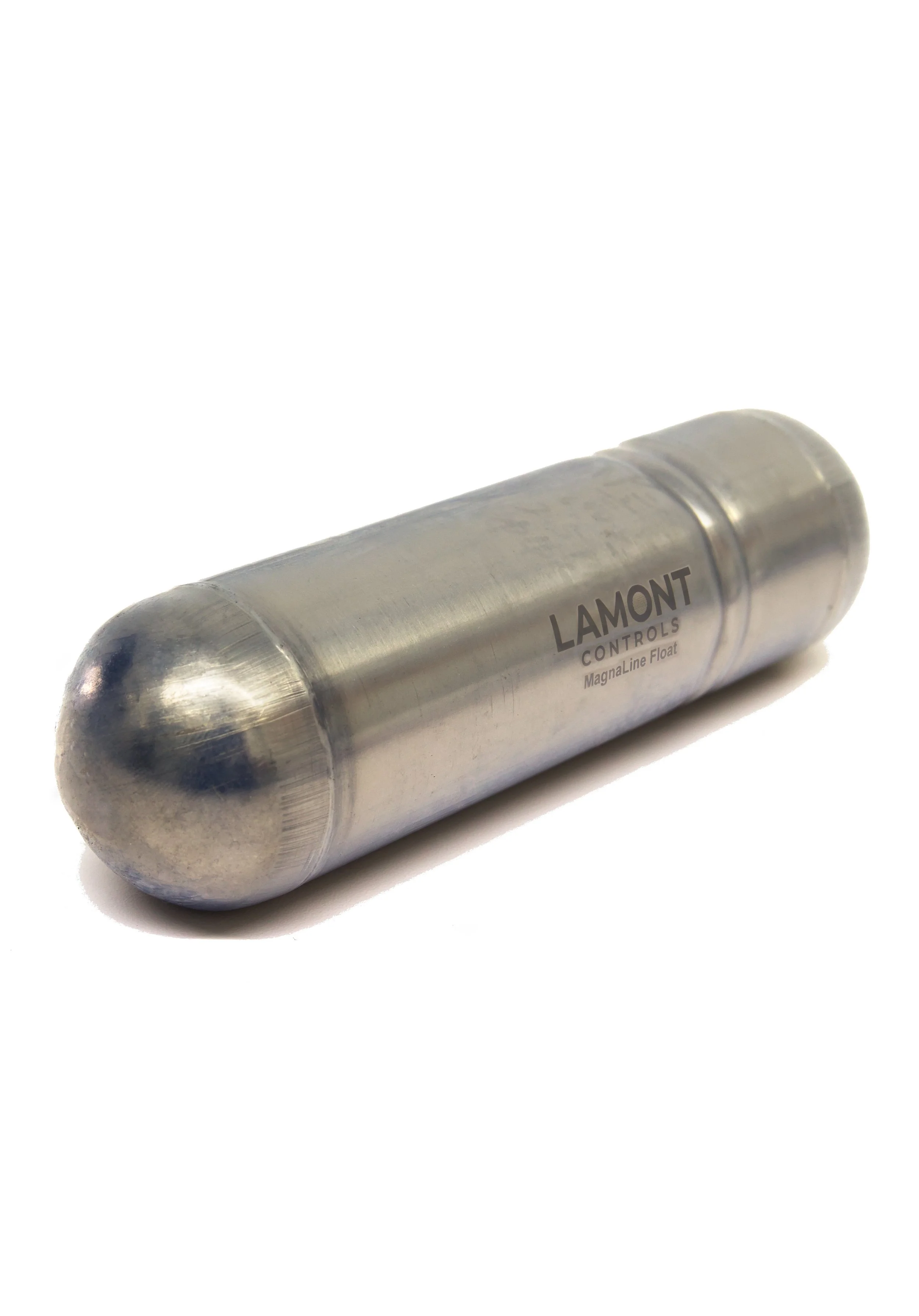
Titanium MagnaLine Float
High-strength titanium offering superior buoyancy-to-weight ratio for precision tracking in low-density and high-pressure applications.
-
![]()
Stainless Steel MagnaLine Float
Rugged 316/316L stainless steel construction designed for dependable performance in general industrial process services.
-
![]()
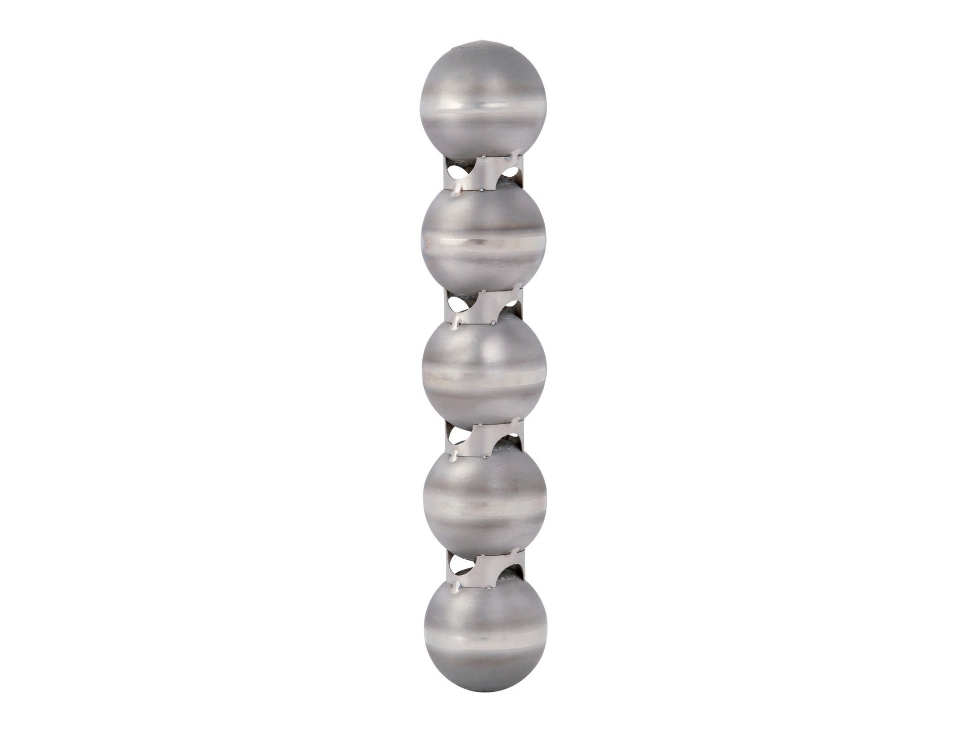
High-Pressure MagnaLine Float
Reinforced float with ball-segment geometry for high-pressure service.
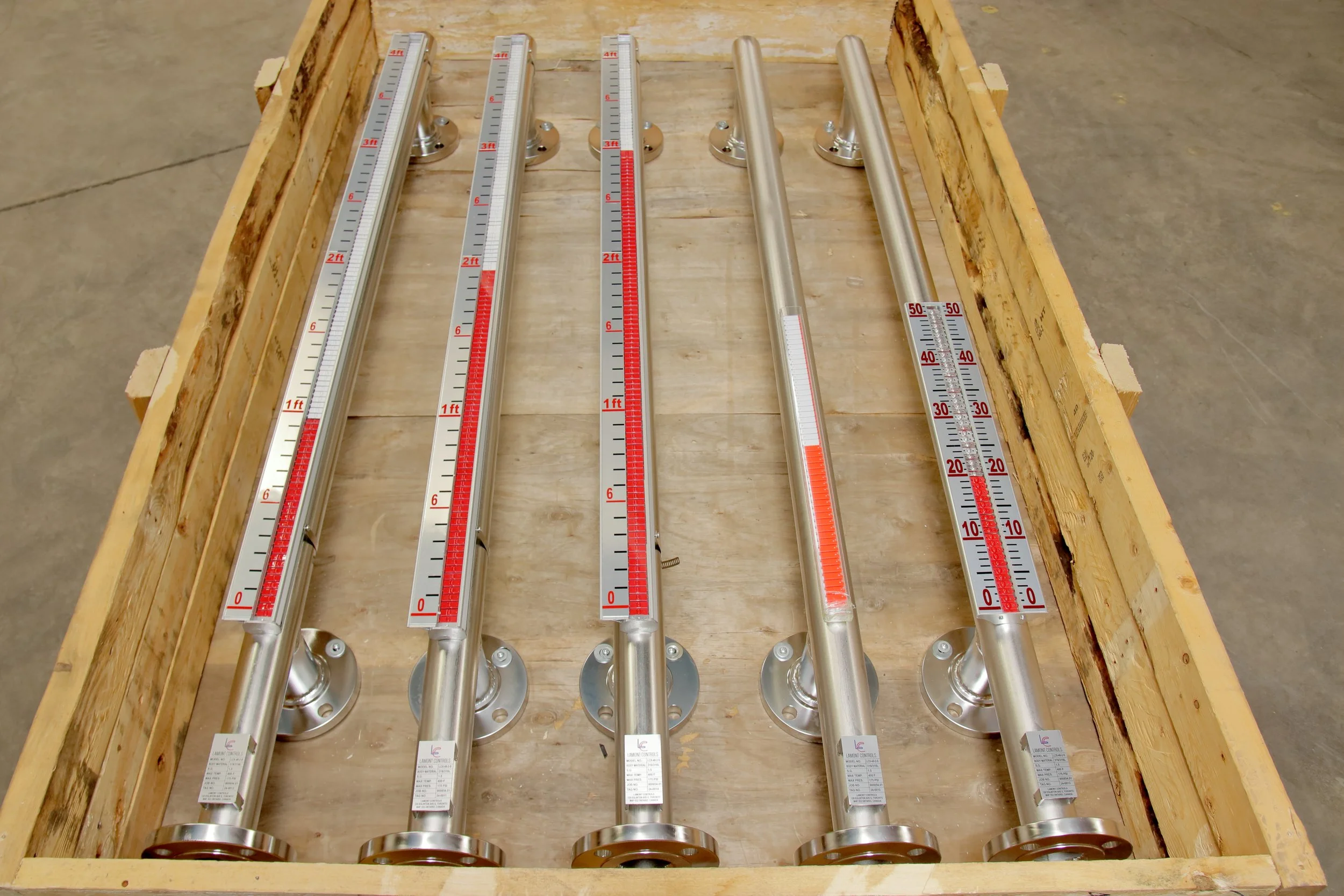
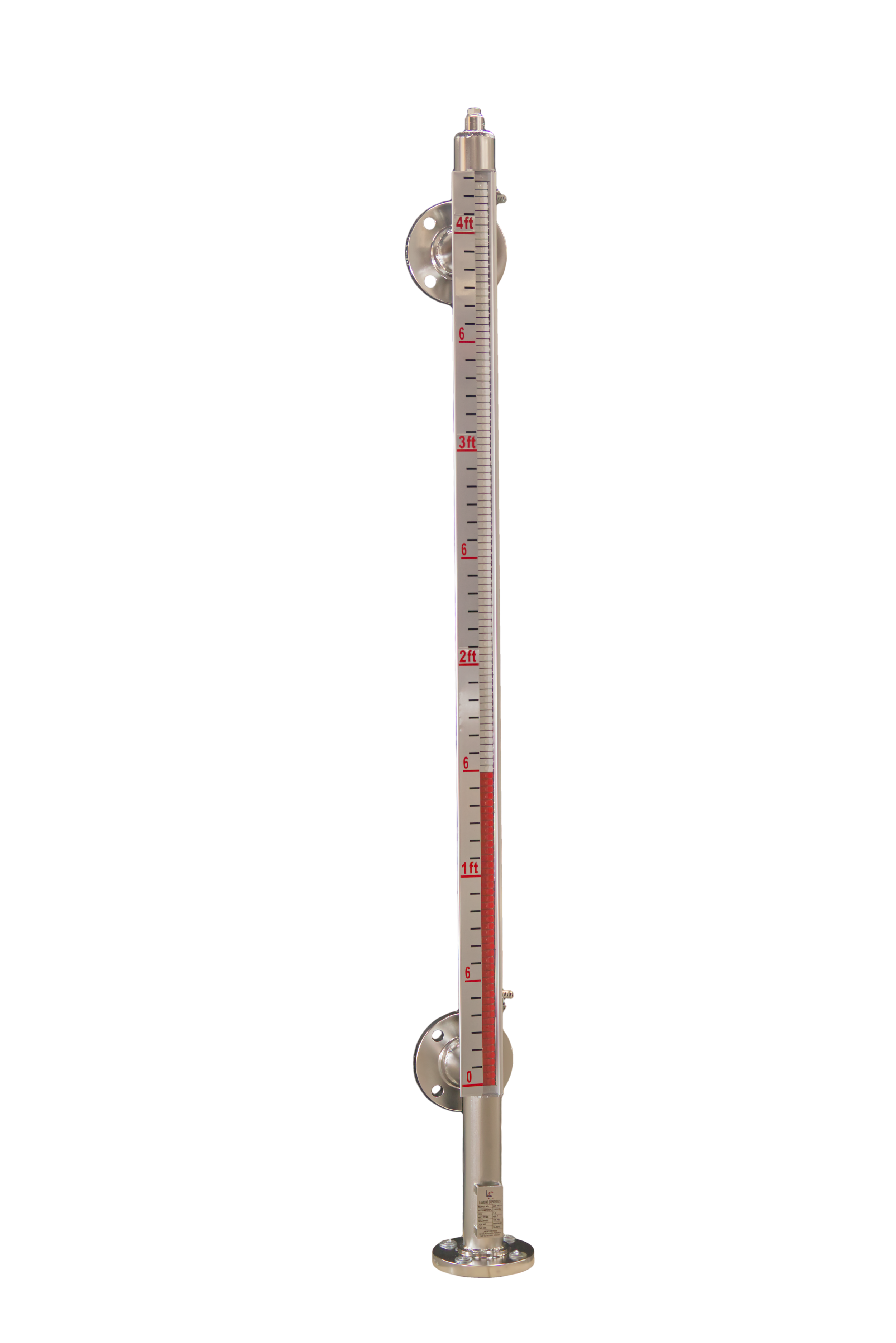
ClearView™ Indicator System
High-Visibility Process Isolation
The ClearView™ system delivers clear, continuous local level indication without mechanical linkages or process penetration. Driven by the internal float’s magnetic field, the external indicator remains completely isolated from the process, ensuring reliable performance unaffected by pressure, temperature, or aggressive fluid conditions. Multiple indicator styles, robust housing materials, sealing options, and temperature ratings are available to suit a wide range of operating environments.
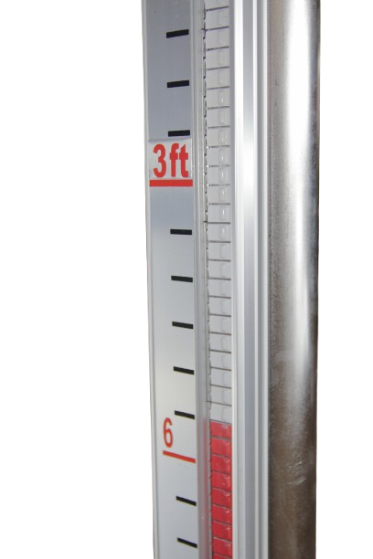
Custom Scales and Readout Units
Indicator assemblies may be supplied with custom scale markings tailored to application requirements. Standard linear units are available in inches, feet, or metric, alongside dual scales or volumetric readouts (gallons, liters) derived from vessel geometry.
Custom scales are generated based on supplied drawings, strapping tables, or dimensional data to ensure accurate correlation between the indicated level and actual vessel volume. This enables direct interpretation of level information in application-specific units without manual conversion.
-
![]()
Black etched aluminum scale indicator with high-contrast markings, resistant to UV exposure, abrasion, and chemical attack for long-term industrial service.
-
![]()
Transparent PVC indicator housing without scale, providing direct visual level indication for chemically aggressive, low-temperature service.
-
![]()
Silver etched aluminum scale indicator providing durable, high-visibility level indication for general industrial environments.
-
![]()
PVC roller-style indicator with integrated scale, designed for corrosive service at lower operating temperatures.
-
![]()
Hermetically sealed indicator assembly with stainless steel scale and frame, intended for harsh, humid, or washdown environments.
-
![]()
Indicator assembly with dual scale markings for simultaneous display of level in two units, such as height and volume, based on application data.

Principle of Operation
How It Works
1. Float Mechanism
A sealed MagnaLine™ float containing a permanent magnetic assembly is designed to remain buoyant within the process liquid based on the fluid’s specific gravity.
As the liquid level rises or falls, the float moves correspondingly within the chamber.
2. Magnetic Coupling
The float’s magnetic field is coupled to the external ClearView™ visual indicator mounted on the chamber.
This ensures the indicator moves synchronously with the float, providing an accurate representation of liquid level without direct process contact.
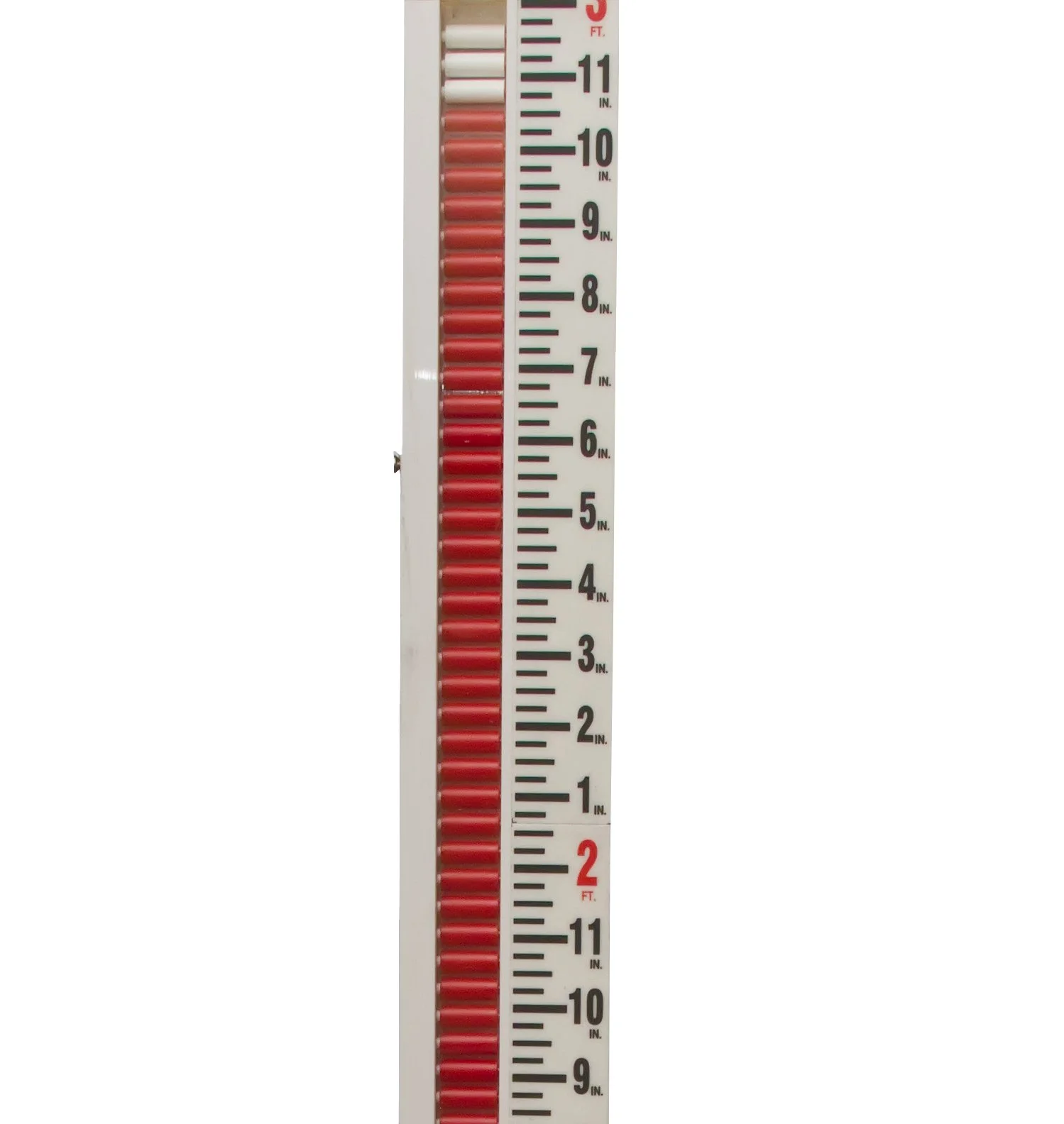
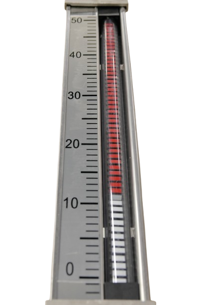
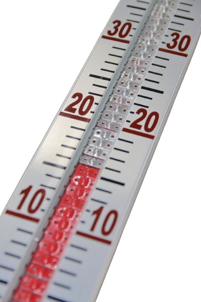
3. Visual Indication
The indicator is comprised of rotating flags or rollers in contrasting colors that change position to reflect liquid and vapor levels.
This provides clear, continuous visual indication without direct process contact, supporting reliable operation across typical pressure and temperature ranges.


Sealed and Non-Invasive Design
Fully Contained Process: The process fluid remains completely contained within the chamber.
No Wetted Indication Components: No glass, probes, or electronics are exposed to the process.
Leak and Emissions Reduction: Eliminates potential leak paths, emissions, and contamination risk.
Magnetic level gauges provide a sealed, non-invasive method of liquid level indication for industrial process applications where safety, reliability, and maintenance access are critical. Here’s why MLGs are the superior choice:
Why Use Magnetic Level Gauges?
Improved Safety Compared to Sight Glasses
No Fragile Glass: Removes glass components from the process line entirely.
Shatter Risk Elimination: Avoids failures caused by pressure spikes, thermal shock, or impact.
Reduced Exposure Risk: Minimizes personnel exposure to hazardous or corrosive fluids.
Low Maintenance and Long Service Life
Externally Mounted Components: Indicator assemblies remain isolated from the process fluid.
No Degrading Wetted Parts: Eliminates seals, gaskets, or electronics that deteriorate over time.
Simplified Inspection: Reduces inspection effort and overall lifecycle maintenance requirements.
Mechanical Reliability
Magnetically Coupled Operation: Uses a float and external indicator linked through magnetic coupling.
Non-Electronic Indication: No electronics, power supply, or calibration required for local indication.
Harsh Environment Performance: Maintains reliable operation where electronic sensors may struggle.
Technical Specifications
Chamber Configurations
Side-Side, Top-Bottom, Top-Side, Bottom-Side Dual-chamber construction available with dedicated float chamber and secondary instrumentation chamber (available upon request)
Chamber Diameters
1.5", 2" (schedule and material per design requirements) Larger diameters available upon request
Measuring Range
Standard lengths up to 40 ft (12.2 m), depending on material and support conditions. Extended lengths available upon request
Accuracy
Typical: ±10 mm (±0.4 in), subject to float design and application conditions
Specific Gravity Range
≥ 0.34 (minimum), subject to float design and application conditions
Pressure Range
Full vacuum to 3,265 psig (250 bar), depending on material, temperature, and configuration
Temperature Range
–200 °C to +450 °C (–328 °F to +842 °F), depending on chamber material and application conditions
Float Materials
Standard: Titanium
Optional: SS316, Hastelloy, Monel
Coated/Lined: ECTFE, PTFE, PFA, ETFA
Chamber Materials
SS304, SS316, Hastelloy, Monel,
Optional linings and coatings available upon request (e.g., ECTFE/Halar®, ETFE/Tefzel®)
Construction Codes & Approvals
Industrial Grade (CWB Certified CSA W47.1)
ASME B31.1 (Power Piping Standard)
ASME B31.3 (Process Piping Standard)
Process Connections
Flanged, threaded (NPT, BSP), or welded connections (Weldolet®, Sockolet®) DIN flanges and SAE fittings available
Standard sizes: ½", ¾", 1", 1.5", 2"
Larger sizes and custom connections available upon request, subject to application review.
Indicator Options
Standard Indicator Assemblies
Stainless steel flags, aluminum housing, no scale, max 300 °C
Stainless steel flags, aluminum housing, with scale, max 300 °C
Thermoplastic Indicator Assemblies
PVC flags, transparent PVC housing, no scale, max 80 °C
PVC rollers with PVC scale, max 80 °C
High-Temperature Indicator Assemblies
Stainless steel flags, aluminum housing with scale, max 450 °CSealed Indicator Assemblies
Hermetically sealed stainless steel scale and frame with PVC flags, max 80 °C or 300 °C
Hermetically sealed, argon-purged stainless steel scale and frame with PVC flags, max 80 °C or 300 °C
Optional -No indicator
Scale Options
Feet & Inches (Imperial)
Meters/Centimeters (Metric)
Percent (0–100%)
Volume indication (Gallons or Liters, based on customer-provided reference)
Custom
No Scale
Scale Material
Etched aluminum scale resistant to UV exposure, abrasion, and chemical attack. Marking compliant with MIL-STD-130N and related identification standards. Optional non-metallic scales available for enhanced chemical resistance.
Vent & Drain Options
Threaded (MNPT or FNPT) or flanged connections
Standard Sizes: ½", ¾"
Alternate connection types (e.g., SAE) and larger sizes available upon request, subject to application review
Surface Finishes & Treatments
Passivation: Full-immersion passivation in accordance with ASTM A380 / ASTM A967 (stainless steel components only)
Electropolishing: Internal and/or external surfaces in accordance with ASTM B912, where applicable
Mechanical Polishing: Internal and/or external surfaces available upon request
Optional: Painted or powder-coated external finishes for environmental protection or color coding
Testing & Quality Assurance
Full material traceability and documentation maintained throughout the manufacturing process
Non-Destructive Testing (NDE) performed in accordance with applicable project-specified codes and standards (e.g., ASME B31.1, ASME B31.3, or other governing codes), where required:
Visual Testing (VT) of welds and final assembly
Radiographic Testing (RT) of butt welds, where applicable
Dye Penetrant Testing (PT) of fillet welds, where applicable
Positive Material Identification (PMI) for alloy verification, where specified
Pressure Testing:
Hydrostatic testing conducted at 1.5 × design pressure, in accordance with applicable ASME standards
Additional inspection, testing, and documentation available upon request
Product Literature & Downloads
Technical documentation provided for application review, specification, and quotation support.
Product Overview
Specification Sheet