Analytics, advertising measurement and session recording stay off unless accepted. They show how the site is used and which advertising brings enquiries. The choice can be changed at any time under Cookie settings at the foot of each page. Privacy policyAnalytics, advertising measurement and session recording stay off unless accepted. They show how the site is used and which advertising brings enquiries. The choice can be changed at any time under Cookie settings at the foot of each page. Privacy policyThis site uses analytics and advertising cookies to show how it is used and which advertising brings enquiries. Decline turns them off. Session recording runs only after Accept. The choice can be changed at any time under Cookie settings at the foot of each page. Privacy policy
Electropolished stainless chamber Without an indicator
Level bridles and external chambers
A level bridle gives every level instrument on a vessel one shared liquid column and one pair of vessel nozzles. The gauge, transmitter and switches mount on the bridle, not on separate vessel penetrations. The bridle ships with its isolation valves, which allow the instruments to be serviced without draining the vessel. Lamont supplies level bridles and external chambers built to the same standard as its magnetic level gauge chambers: 316 stainless steel, welded to ASME B31.3, pressure tested and documented.
Material, standard
SS316Hastelloy, Monel K-500, Inconel 625, other alloys on request
Construction code
ASME B31.3or B31.1; or industrial grade
ASME B16.5 flange class, to
Class 1500Class 2500 flanges built to order
Standpipe, standard
3 inbridle ships with isolation valves and a ¾ in valved vent and drain
Design pressure and temperature per job, stated on the approval drawing
Orders from outside Canada. Quotations in US dollars, Ex Works (EXW) Toronto as standard, with freight to site (DAP) quoted on request. Worldwide supply
Definition
What is a level bridle
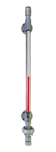
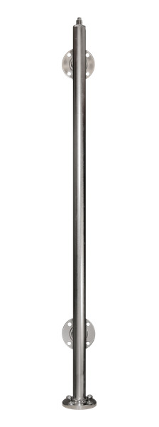
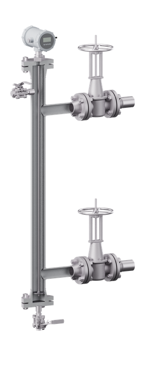
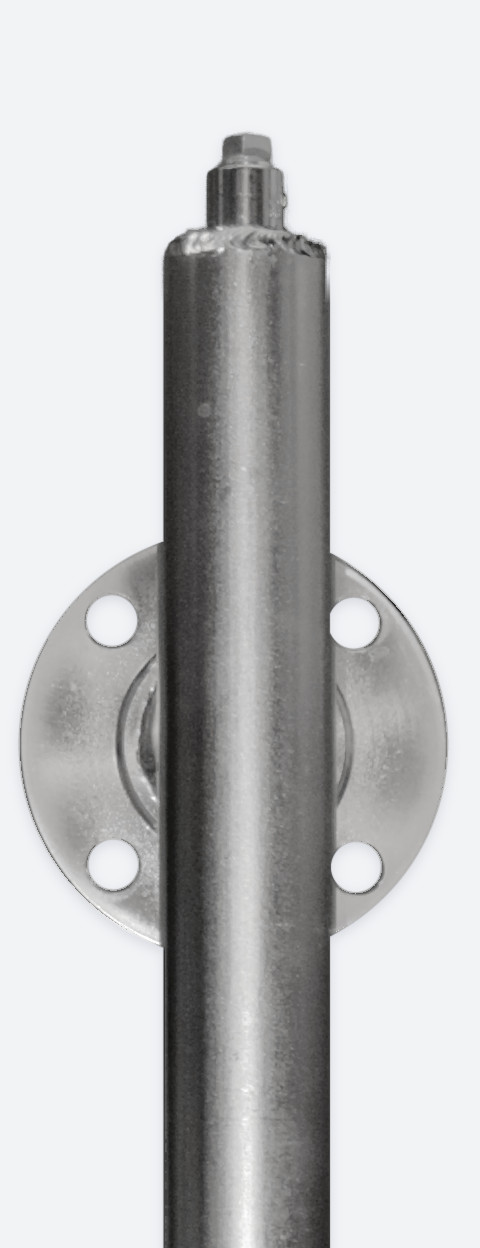
Electropolished stainless chamber, without an indicator: the standpipe and a flanged side connection.
A level bridle is a vertical standpipe mounted beside a vessel and connected to it at two points: one below the lowest level to be measured and one above the highest. Liquid enters through the lower connection and stands in the bridle at the same level as in the vessel, so every instrument on the bridle reads the vessel level.
Plants fit bridles to separators, drums and tanks that carry more than one level instrument, so that one pair of vessel nozzles serves the gauge, transmitters and switches together.
Parts of a level bridle
Standpipe
The vertical column: 3 in pipe as standard on a Lamont bridle; other sizes on request
Vessel connections
Two, matched to the vessel nozzles: flanged, threaded or welded, ½ to 4 in
Isolation valves
One on each vessel connection, to shut the bridle off from the vessel. Supplied by Lamont with the bridle
Instrument branches
Side branches for the gauge, transmitters and switches, with spares for future instruments
Top flange
Sized to a top-mounted transmitter
Vent and drain
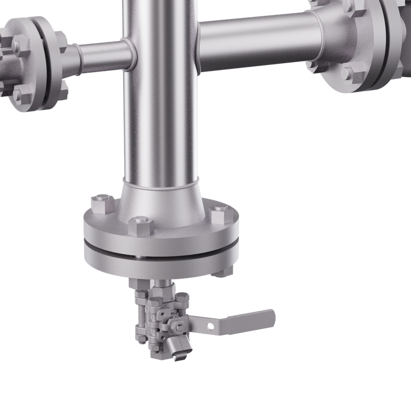
¾ in valved vent at the top and valved drain at the bottom, for venting, draining and flushing the bridle
Application
Bridles and external chambers
Bridle or chamber
Level bridle
A vertical standpipe connected to a vessel at two points, carrying several level instruments on one liquid column. It reduces the number of vessel nozzles and lets instruments be isolated and serviced while the vessel stays in service.
External chamber
Houses one instrument, such as a guided wave radar probe. A bridle carries several instruments on one standpipe. Lamont supplies both, and a bridle can include a chamber section for a top-mounted transmitter.
Why use a bridle
Fewer vessel nozzles. Two vessel connections serve every instrument.
Maintenance without shutdown. With the isolation valves closed and the bridle drained, an instrument can be serviced while the vessel stays in service.
Consistent readings. Every instrument measures the same liquid column, so the gauge, transmitter and switches agree.
A stable liquid surface. The chamber settles turbulence and foam from the vessel, which benefits radar instruments.
Provision for future instruments. A spare branch accepts a new instrument without a vessel modification.
Product
Configurations
Bridles, external chambers and gauge bridles
Render · instrument bridle
Instrument bridle
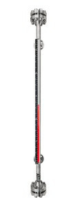
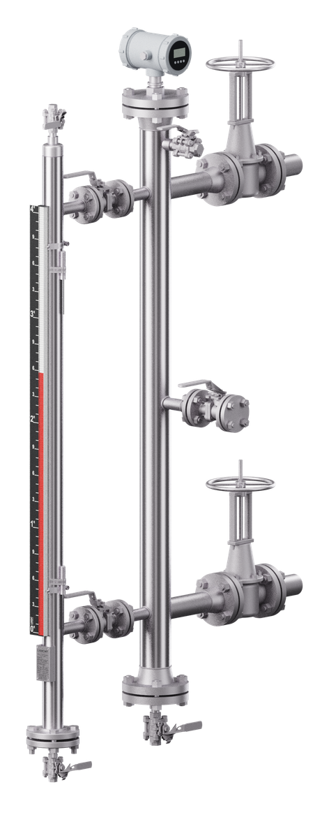
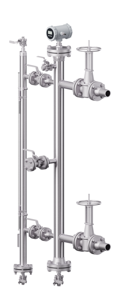
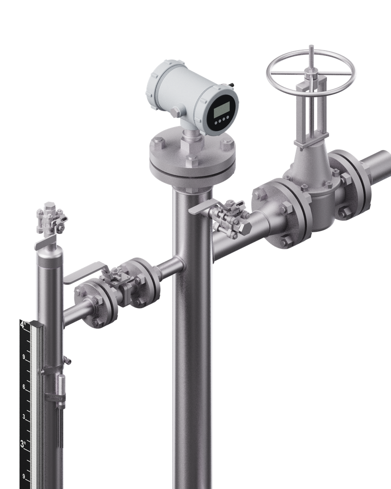
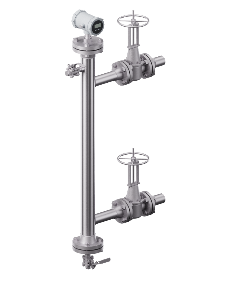
A vertical standpipe joined to the vessel at the top and bottom, with a branch connection for each instrument: a magnetic level gauge, one or more transmitters, and high and low level switches. Spare branches can be added for future instruments.
Render · chamber for a top-mounted radar
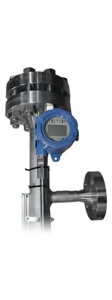
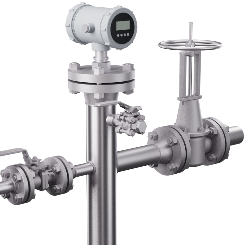
External chamber for a top-mounted transmitter
A chamber sized to the guided wave radar probe or other top-entry transmitter. The top flange is matched to the instrument, with side–side or side–bottom process connections to suit the vessel nozzles.
Render · level package
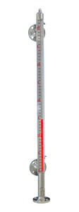
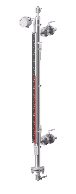
Bridle with a Magnamont™ gauge
In 316 stainless steel, the bridle can serve as the gauge chamber. A single standpipe then provides local indication, a LevelSync™ transmitter and SPDT clamp-on switches, with no additional vessel nozzles.
Render · instrument bridle from aboveRender · drain and lower isolation valveRender · chamber for a top-mounted radar
Instruments. Lamont supplies its own Magnamont™ gauges, with LevelSync™ transmitters and SPDT clamp-on switches mounted on the gauge. Instruments from other manufacturers are supplied by others, and Lamont supplies the bridle or chamber to suit them. For an existing transmitter, send its datasheet and the vessel connections.
Instruments
Which instruments mount on a level bridle
Connections set by each instrument's datasheetInstruments and their connections
Instrument
How it measures
On the bridle
Magnetic level gaugeLocal indication
A float with magnets rides on the liquid inside a chamber and turns a column of flags on the outside.
In 316 stainless steel the bridle itself can be the gauge chamber, so the gauge needs no branches of its own. Lamont supplies the Magnamont™ for this.
Magnetostrictive transmitterContinuous signal
Senses the position of a magnetic float along a sensing tube and gives a continuous level signal.
Clamped to the outside of a magnetic level gauge chamber, it reads the gauge float with no wetted parts and no extra branch: the LevelSync™, 4–20 mA with HART®. Top-entry probes carry their own float in a chamber section.
Guided wave radarContinuous signal
A microwave pulse runs down a probe and reflects from the liquid surface; the travel time gives the level.
The probe enters through a top flange into a chamber section sized to it. The chamber also settles turbulence and foam.
DisplacerContinuous signal or alarm
A displacer hangs in the liquid; its apparent weight falls as the level rises, and the instrument converts that change to a signal.
Usually in its own cage, joined to the bridle by side branches spaced to the instrument datasheet.
Level switchesHigh and low alarms
Float, displacer or vibrating switches change state when the liquid reaches the switch.
On flanged or threaded side branches at the alarm heights. On a magnetic level gauge, SPDT clamp-on switches mount outside the chamber and need no branch.
Supply. As standard, a bridle ships with its isolation valves; an external chamber is supplied with them when specified. When ordered, Lamont supplies the instruments: Magnamont™ gauges, LevelSync™ transmitters and SurePoint™ SPDT clamp-on switches. Instruments from other manufacturers are supplied by others; the bridle is built around them, from their datasheets.
Comparison
Level bridle vs direct vessel mounting
Comparison and which to choose
On a level bridle
Direct on the vessel
Vessel nozzles
Two, shared by every instrument on the bridle
One or two for each instrument
Servicing an instrument
Isolation valves closed and bridle drained; the vessel stays in service
Depends on the instrument and its nozzle; some need the vessel isolated or drained
Agreement between instruments
Every instrument reads one liquid column
Each instrument reads at its own nozzle
Turbulence and foam
Settled in the standpipe
Seen by the instrument; inlets, mixers and internals can disturb the reading
Adding an instrument later
Fitted to a spare branch
A new vessel nozzle, which is a vessel modification
Liquid temperature
Can run cooler than the vessel; heat tracing and insulation keep it close
Same as the vessel
Plugging
A small bore can plug in solids-bearing or waxy service, or freeze
Less pipework to plug
Space and parts
Standpipe, valves and supports beside the vessel
No extra pipework
Which to choose
A bridle is justified when one vessel carries several level instruments, when instruments must be serviced with the vessel in operation, or when vessel nozzles are limited.
Direct mounting often suits a single instrument on a vessel that already has a suitable nozzle.
Temperature. Liquid in an uninsulated bridle cools toward ambient. Cooler liquid is denser, so the column in the bridle stands slightly lower than the level in the vessel. Heat tracing and insulation, offered as options, keep the two close.
Construction
Construction and materials
Engineered to order · confirmed on the approval drawingChamber and connections
Upper end of an electropolished stainless chamber, without an indicator: welded end cap with a plugged top connection, above the upper flanged side connection.
Every bridle and chamber is engineered to order. The pipe, flange class and design conditions, the nozzle orientation and the test pressure are confirmed on an approval drawing before fabrication starts. The approval drawing is issued after the purchase order.
Bridle or chamber
Pipe size
3 in (standard) · other sizes on request
Material
SS316 (standard). Hastelloy, Monel K-500, Inconel 625 and other alloys on request
Length
Engineered to order
Design pressure and temperature
Per job, stated on the approval drawing
Options
Heat tracing and insulation · Magnamont™ gauge on the bridle, with LevelSync™ transmitter and SPDT clamp-on switches · stainless tag plate
Bridle supplied with
Isolation valves on both vessel connections · ¾ in valved vent and drain
Chamber supplied with
Isolation valves when specified
Instruments
Magnamont™ gauge, LevelSync™ transmitter and SurePoint™ switches from Lamont when ordered · other instruments supplied by others
Connections
Process connections
Flanged · female NPT · male NPT · Weldolet · Sockolet · custom. ½ to 4 in
Flange class
ASME B16.5 Class 150 to 1500; Class 2500 flanges built to order · DIN PN16 to PN40 · JIS 5K to 20K
Instrument connections
Top flange or NPT sized to the instrument · side branches for gauge, transmitter and switches
Vent and drain
¾ in valved vent and drain (standard on bridles) · flanged or custom on request
Ratings. Pressure and temperature ratings depend on materials, connections and configuration, and are confirmed at quotation.
Quality
Codes, testing and documentation
Codes, testing and documentation
Codes and testing
Construction code
ASME B31.3 Process Piping or ASME B31.1 Power Piping; or industrial grade
Pressure test
Pressure tested before shipment; hydrostatic test at not less than 1.5 × design pressure where specified. The test pressure is stated on the approval drawing
Review and documents
With the quotation
Price and lead time, from the vessel connections, instruments and design conditions. Packed dimensions and weight on request, for freight planning
After the purchase order
Approval drawing, for review and signature before fabrication. It confirms pipe, flange class, design conditions, nozzle orientation and test pressure
With the shipment
Material test reports for pressure parts and hydrostatic test reports, available. Commercial invoice and packing list. Certificate of origin, chamber-of-commerce certified, on request
Quality and document requirements beyond those listed here are reviewed against the purchase specification at quotation. Attach the inspection and test plan, witness points or document list to the request.
Applications
Selected projects
Gauges with transmitters or switches · customer names withheldShipped projects
Enquiry
What to send for a quotation
A complete request is quoted fastest. Send what is available, and Lamont Controls Engineering will ask for the rest.
Vessel connectionsNozzle sizes, flange class and centre-to-centre distance.
Instruments to mountMake, model and datasheet for each, including probe length and mounting flange.
Process conditionsFluid, specific gravity, design pressure and temperature.
Material and codeWhere the project specification calls for them.
Quantity and required dateOne request can cover several bridles; give each a tag number.
A drawing or sketchWhere available, with the P&ID.
Complete the fields below, or attach the datasheet, requisition, tag list or a sketch: with a file attached, the bridle fields are optional. Fields marked * are required for pricing.
For several bridles, send one request with a tag number for each, or attach the tag list. For a general enquiry, select Quick message.
What happens nextLamont Controls Engineering reviews the request and replies within 1 to 3 business days with a quotation. The approval drawing is issued after the purchase order.
A level bridle is a vertical standpipe connected to a vessel at two points, carrying several level instruments on one liquid column. It reduces the number of vessel nozzles and lets instruments be isolated and serviced while the vessel stays in service.
What is the difference between a bridle and an external chamber?
An external chamber houses one instrument, such as a guided wave radar probe. A bridle carries several instruments on one standpipe. Lamont supplies both, and a bridle can include a chamber section for a top-mounted transmitter.
Which instruments can mount on a level bridle?
Magnetic level gauges, magnetostrictive and guided wave radar transmitters, displacers, and high and low level switches. Where the bridle is also the chamber of a magnetic level gauge, a clamp-on magnetostrictive transmitter and SPDT clamp-on switches read the gauge float from outside, with no extra branches.
Can a magnetic level gauge mount on the bridle?
Yes. In 316 stainless steel, the bridle can serve as the gauge chamber. A Magnamont™ gauge then indicates level along the bridle with no additional vessel nozzles.
Does Lamont supply the transmitter?
Yes, when it is ordered. Lamont supplies Magnamont™ gauges, LevelSync™ transmitters and SurePoint™ SPDT clamp-on switches mounted on the gauge. Instruments from other manufacturers are supplied by others, and Lamont supplies the bridle or chamber to suit them. As standard, the bridle ships with its isolation valves.
Can Lamont supply a chamber for an existing transmitter?
Send the transmitter datasheet and the vessel connections. Lamont Controls Engineering reviews them and replies with a quotation for a chamber sized to the instrument. Isolation valves are supplied with the chamber when specified.
What materials and codes are bridles built to?
316 stainless steel as standard, with Hastelloy, Monel K-500, Inconel 625 and other alloys on request, welded to ASME B31.3 Process Piping or ASME B31.1 Power Piping, or industrial grade. The standpipe is 3 in pipe as standard; other sizes on request. Flanges are ASME B16.5 Class 150 to 1500, with Class 2500 flanges built to order.
How is a bridle tested and documented?
Each bridle is pressure tested before shipment, with a hydrostatic test at not less than 1.5 × design pressure where the order specifies it. The test pressure is stated on the approval drawing, which is issued after the purchase order. Material test reports for pressure parts and hydrostatic test reports are available.