Lamont Controls 1-833-7LAMONT Request a quotation Call

Cookies on this site

Analytics, advertising measurement and session recording stay off unless accepted. They show how the site is used and which advertising brings enquiries. The choice can be changed at any time under Cookie settings at the foot of each page. Privacy policy

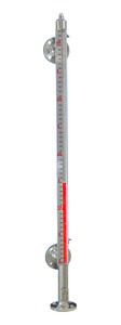
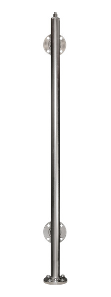
Magnamont magnetic level gauge, full length: side–side, with flanged side process connections, a welded cap and vent at the top, a bolted bottom flange, and a scale in feet beside red and white indicator flags
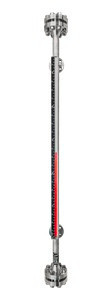
Magnamont™ · side–side
Flanged side connections

Replace a glass level gauge with a magnetic level gauge

Magnamont™ and Fortimag™ built to ASME B31.1 or B31.3 as specified ·Pressure tested before shipment · Test reports available · Made in Canada

Tubular, reflex and transparent sight glasses show the liquid through glass held by gaskets and bolted covers. The glass etches and stains, the gaskets need replacing, a long range is read across several sections, and any switch or transmitter needs its own nozzles. A Lamont magnetic level gauge replaces the sight glass with one welded or bonded chamber and shows the level on high-contrast flags outside it. It is built to the same centre-to-centre, connection size, flange class and facing as the installed gauge, so it can mount on the same nozzles. A nameplate photo, a datasheet, or the centre-to-centre and connections is enough to start a quotation.

Pressure, to
5,000 psigFortimag™ · Magnamont™ to 3,400 psig
Temperature
−40…+842 °F−40…+450 °C · Magnamont™, Fortimag™
C-C length, standard to
18.5 ft222 in (5,640 mm); longer on request
Process connections
½ to 4 inflanged, threaded or welded

Made in Canada

Retrofit

Why replace a glass gauge

  • No glass in the pressure boundary. One welded 316 stainless chamber (Magnamont™, Fortimag™) or bonded CPVC or PVDF chamber (Polysight™) replaces the glass, gaskets and cover plates. The indicator mounts outside the chamber, so damage to the indicator does not open the process.
  • Readable from across the plant. High-contrast flags show a solid band of colour up to the level. Operators read the level from the floor, without approaching hot equipment with a light.
  • One chamber over the full range. Standard lengths to 18.5 ft (222 in, 5,640 mm) centre-to-centre are built in one chamber, with longer lengths on request. There are no blind lengths between sections.
  • Nothing in the indicator to clean or replace. The indicator is not in contact with the process, so there is no glass to etch, stain or coat. The chamber is flushed through its drain during routine maintenance.
  • Alarms and a signal on the same nozzles. SurePoint™ SPDT clamp-on switches and a LevelSync™ transmitter mount outside the chamber. One pair of nozzles provides local indication, alarms and a 4–20 mA signal.
  • Piping-code construction, pressure tested. Magnamont™ and Fortimag™ are built with ASME B31.1 or B31.3 construction options. Pressure tested before shipment; hydrostatic test at not less than 1.5 × design pressure where specified. MTRs and test reports available.
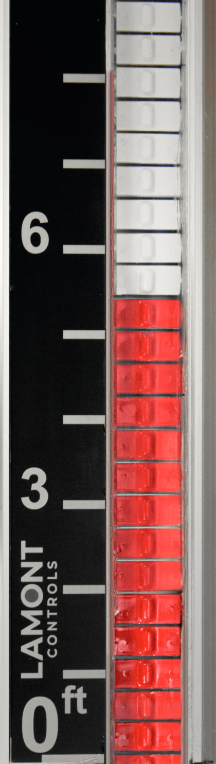
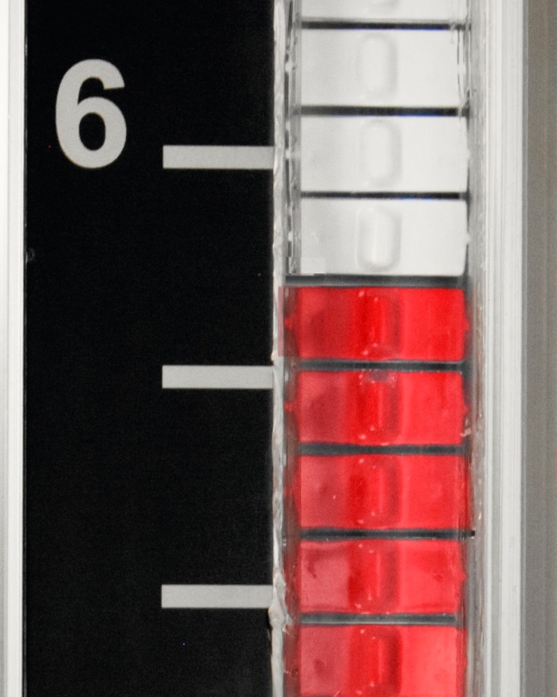
Close-up of a Magnamont indicator with a black etched scale in feet: red flags below the liquid level and white flags above, with the Lamont Controls mark at 0 ft
ClearView™ flags beside a black etched scale: red below the level, white above. Nothing in the indicator is wetted.

How a magnetic level gauge works: full principle of operation

Comparison

Glass gauges and magnetic level gauges compared

Each row lists the Lamont magnetic level gauge first, then the three glass gauge types.

Tubular, reflex and transparent glass gauges compared with a Lamont magnetic level gauge
Tubular glass Reflex glass Transparent glass Magnetic level gaugeMagnamont™ · Fortimag™ · Polysight™
How it shows the levelThe liquid in a glass tube between two gauge valves, usually behind a guardOne flat glass with prism grooves: the liquid shows dark, the vapour space brightThe liquid between two flat glasses, viewed through the gaugeFlags outside a sealed chamber, turned by the float's magnet: red below the level, white above
Pressure boundaryThe glass tube, sealed at each endGlass and gasket under a bolted cover, on every sectionTwo glasses and gaskets under bolted covers, on every sectionOne welded 316 chamber (Magnamont™, Fortimag™) or bonded CPVC or PVDF chamber (Polysight™). No glass
PressureLow-pressure serviceSet by the glass size, construction and temperature; falls as temperature risesSet by the glass size, construction and temperature; falls as temperature risesFull vacuum to 5,000 psig (345 bar) Fortimag™, 3,400 psig (234 bar) Magnamont™, 150 psig (10 bar) Polysight™
TemperatureLimited by the tube and its sealsLimited by the glass and gaskets; hot water and steam etch the glassLimited by the glass and gaskets; mica shields protect the glass in hot water and steam−40 to +842 °F (−40 to +450 °C) Magnamont™ and Fortimag™, lower temperatures on application review; −4 to +248 °F (−20 to +120 °C) Polysight™
Visible rangeShort lengthsBuilt in sections; blind lengths between sections unless gauges overlapBuilt in sections; blind lengths between sections unless gauges overlapOne chamber, standard to 18.5 ft (222 in, 5,640 mm) C-C; longer lengths on request
ReadingClose upClose up, with light on the glassClose up, often with an illuminator behind the gaugeHigh-contrast flags, readable from across the plant
What is seenThe liquid itselfThe liquid surface, in clean, clear liquidsThe liquid itself: colour, clarity and layersThe level only. Interface service with a float set for the second liquid (option INT)
UpkeepCleaning; tube and seal replacementCleaning; glass and gasket replacement once etched or stainedCleaning; glass, gasket and mica shield replacementIndicator not in contact with the process; chamber flushed through the drain
Alarms and signalSeparate instruments, often on separate nozzlesSeparate instruments, often on separate nozzlesSeparate instruments, often on separate nozzlesSurePoint™ SPDT clamp-on switches and a LevelSync™ 4–20 mA transmitter on the same chamber

Glass gauges are described here in general terms; the rating of an installed glass gauge is on its maker's nameplate and documents. Ratings. Magnetic level gauge pressure and temperature ratings depend on materials, connections and configuration, and are confirmed at quotation.

Where glass remains suitable

  • Short, clean, low-pressure service where an operator is already at the gauge.
  • Where operators need to see the liquid: colour, clarity or foam is judged by eye. A magnetic level gauge shows the level, not the appearance of the liquid.
  • Where a code or the owner's specification requires a direct-reading gauge glass.
  • Purchase price on small gauges. For a short, low-pressure, clean application, a tubular or reflex gauge usually costs less to buy.

Replacement

Fits the existing nozzles

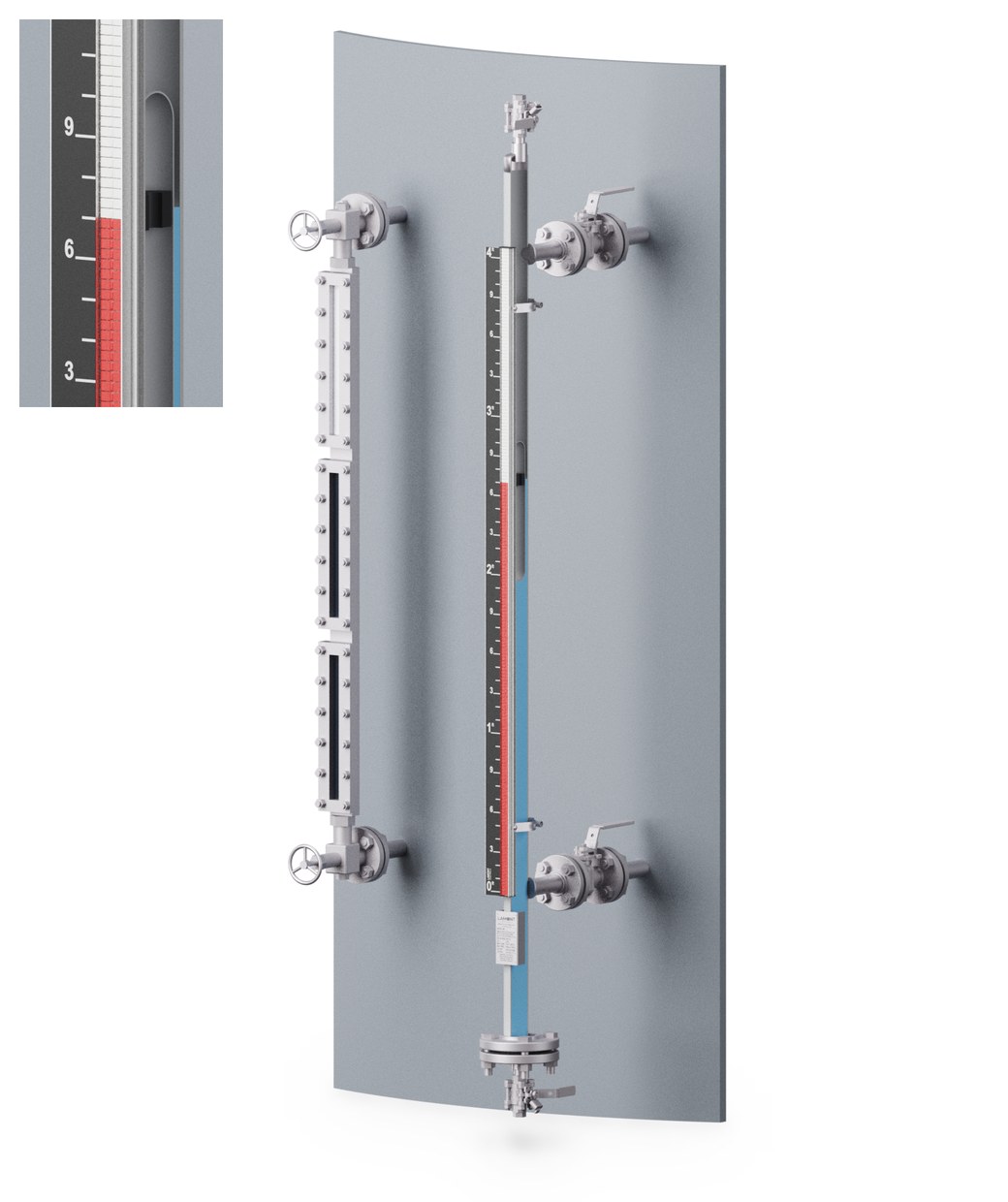
Render of two gauges on the same vessel wall and the same two nozzles. Left: a sectional reflex glass gauge in three bolted sections between two gauge valves; the glass is dark where it holds liquid and silver above, and the level sits in the blind length between two sections, where it cannot be seen. Right: a Magnamont™ magnetic level gauge with an isolation valve on each nozzle, a welded cap and vent, and a bottom flange below the lower nozzle. Its chamber is cut open to show the float with its magnet at the level, and the indicator outside the chamber shows red flags below the level and white flags above; a close-up (detail A) shows the flags, the float magnet and the liquid at one height. The centre-to-centre between the nozzles is the same for both.123456789LevelSame centre-to-centreAAfloat removal

Sectional glass gauge

  1. Gauge valve on each nozzle
  2. Not visible blind length between sections; here it hides the level
  3. Glass section dark where liquid, silver where vapour
  4. Cover bolts

Magnamont™ magnetic level gauge

  1. Cap and vent welded cap on one welded chamber
  2. Isolation valve on each nozzle
  3. Flags outside the chamber red below the level, white above (detail A)
  4. Float its magnet at the level (detail A)
  5. Bottom flange below the lower nozzle, for float removal
Render · A sectional reflex glass gauge and a magnetic level gauge with the same centre-to-centre. The magnetic level gauge reads over the whole centre-to-centre with no blind lengths; in this view the level sits in a blind length of the glass gauge. Its chamber continues below the lower nozzle to the bottom flange, through which the float is removed.

Each replacement level gauge is built to the installed gauge, not to a catalogue length. The centre-to-centre, configuration and process connections are taken from the existing gauge. The chamber material, float and indicator are selected for the fluid and the operating conditions.

Matched to the installed gauge

Centre-to-centreBetween the nozzle centrelines, or the valve outlets where the gauge bolts on; not the length of the glass. Standard to 18.5 ft (222 in, 5,640 mm); longer lengths on request
ConfigurationSide–side · top–bottom · top–side · bottom–side · top-mount
Connection size½ to 4 in NPS on Magnamont™ and Fortimag™; 1 to 2 in on Polysight™ (3 in: consult factory)
Flange class and facingANSI Class 150 to 1500 (Magnamont™) · 150 to 2500 (Fortimag™, Class 2500 built to order) · 150 (Polysight™). Facing taken from the existing flange
Threaded and weldedFNPT or MNPT; Weldolet or Sockolet on Magnamont™ and Fortimag™

Fit, materials and ratings are confirmed at quotation.

Checks before ordering

  1. Space below the gauge. The chamber extends below the lower connection to the bottom flange, through which the float is removed. The dimension is stated on the quotation.
  2. Projection and clearance. Check the distance from the vessel to the gauge centreline, and the space beside the chamber for the indicator and scale near ladders, pipes or walls.
  3. Valves. Glass gauge valves often have ball checks that close if the glass breaks. State whether the existing valves stay or are replaced. Isolation valves on both nozzles allow the gauge to be serviced without draining the vessel.
  4. Fluid and SG at operating temperature, so the float is weighted correctly: minimum SG 0.34 on Magnamont™ and Fortimag™, 0.59 on Polysight™.
  5. Scale units the operators expect: feet and inches, metres, percent, or gallons or litres graduated to the tank.

Retrofits: replacement gauges and partsSpare parts for installed gauges

Automation

Transmitters and switches on the same chamber

On a glass gauge, a level switch or a transmitter is a separate instrument, often on its own nozzles. On a magnetic level gauge, the switches and the transmitter are externally mounted and magnetically coupled to the same float, with no wetted parts and no additional vessel nozzle. They are fitted at the factory or in the field.

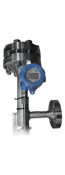
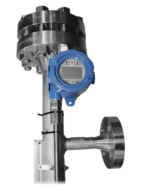
LevelSync magnetostrictive level transmitter fitted beside a gauge chamber, its display head above the sensor

LevelSync™

Magnetostrictive level transmitter

Continuous level output from the gauge float by magnetostrictive time-of-flight sensing. No moving parts and no routine recalibration.

Output
4–20 mA with HART®; Modbus RTU or DDA optional
Accuracy
±0.039 in (±1 mm) inherent
Hazardous area
Intrinsically safe or explosionproof; FM, FMc, ATEX, IECEx, UKCA
Order
Option MLT in the gauge model code
LevelSync™ transmitter
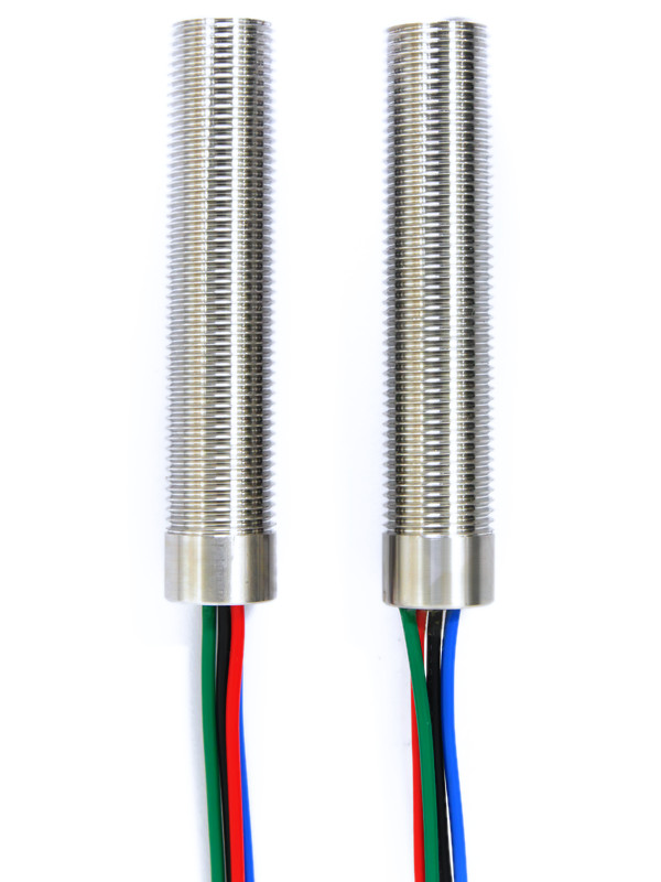
Two SurePoint magnetically actuated level switches with colour-coded leads

SurePoint™

Magnetic point-level switch

Clamp-on switch actuated by the float's magnet through the chamber wall, for high and low level alarms. The set point is the clamp position.

Contact
SPDT, latching
Per gauge
1 to 8 switches
Hazardous area
Class I, Div. 1 (UL 1203); Class II, Groups E, F, G; gas groups confirmed at quotation
Order
Option PLS-1 to PLS-8
SurePoint™ switches

Hazardous-area certifications are held by Lamont's component manufacturing partner and apply to the supplied product. Final certification, temperature class and marking depend on configuration and are confirmed at quotation.

Gauge lines

Selecting the replacement gauge line

Magnamont indicator: black etched aluminum scale beside the indicator flags, white above the liquid level and red below

Magnamont™

SS316 magnetic level gauge

For most glass gauges in process and utility service: storage tanks, process vessels, condensate and feedwater tanks, and utility skids.

PressureFull vacuum to 3,400 psig (234 bar)
Temperature−40 to +842 °F (−40 to +450 °C)
ChamberWelded 316 stainless, slip-on flanges
FlangesClass 150 to 1500
Magnamont™ specifications
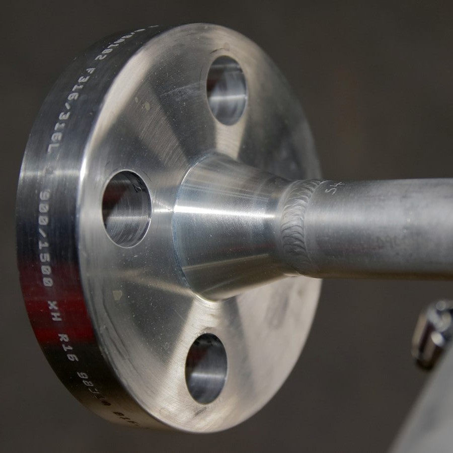
Weld-neck flange on a Fortimag side nozzle, the rim stamped F316/316L 900/1500

Fortimag™

Extreme pressure and temperature service

For high-pressure sight glass replacement, or where the piping specification calls for weld-neck flanges.

PressureFull vacuum to 5,000 psig (345 bar)
Temperature−40 to +842 °F (−40 to +450 °C)
ChamberDouble-flanged 316 stainless, weld-neck flanges, dual stop springs
FlangesClass 150 to 1500; Class 2500 built to order
Fortimag™ specifications
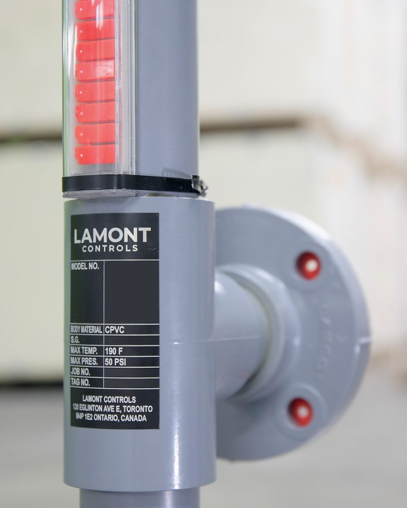
Polysight chamber in grey CPVC with red indicator flags, the Lamont nameplate and a flanged thermoplastic side connection

Polysight™

Thermoplastic, for corrosive service

For glass gauges in acid, caustic or salt service: chemical storage tanks, water and wastewater treatment, and OEM skids.

PressureFull vacuum to 150 psig (10 bar)
Temperature−4 to +248 °F (−20 to +120 °C), material-dependent
ChamberCPVC (standard) or PVDF
FlangesClass 150; 1 to 2 in (3 in: consult factory)
Polysight™ specifications

Swipe for Fortimag™ and Polysight™.

Line selection. Send the photos and the process conditions, and Lamont Controls Engineering recommends the gauge. Send a nameplate photo

Retrofits

Replacement projects

Gauges supplied in place of installed level instruments · customer names withheld

Quality

Quality, testing and documentation

Each replacement is a Magnamont™, Fortimag™ or Polysight™ gauge, built and tested to the technical specification sheet for its line, like any new Lamont gauge. The centre-to-centre and connections are taken from the existing gauge. The design is confirmed on the approval drawing, issued after the purchase order, before fabrication starts.

Build and test sequence · welded chambers, Magnamont™ and Fortimag™

  1. 01

    Approval drawing

    Issued after the purchase order. The design is confirmed on it before fabrication starts.

  2. 02

    Material

    Material traceability is maintained throughout manufacturing.

  3. 03

    Construction code

    Built to ASME B31.1 or ASME B31.3, or industrial grade, as specified in the model code.

  4. 04

    NDE

    Per the governing code where required: visual examination, dye-penetrant examination of fillet welds, radiographic (X-ray) or ultrasonic examination of full-penetration butt welds (Fortimag™), and positive material identification (PMI) where specified.

  5. 05

    Pressure test

    Pressure tested before shipment; hydrostatic test at not less than 1.5 × design pressure where specified.

  6. 06

    Float and indicator

    The float is weighted to the fluid’s specific gravity. The indicator and scale mount outside the chamber.

Polysight™: visual inspection of solvent- and fusion-bonded joints and the assembly, a pressure test before shipment and, where specified, a hydrostatic test with clean water at not less than 1.5 × design pressure (1 hour minimum), then a 24-hour water-fill leak test. Test certificates available.

Documents

MTRs and hydrostatic test reports
Available · Magnamont™ and Fortimag™
Test certificates
Available · Polysight™
Approval drawing
Issued after the purchase order
Certificate of origin
Chamber-of-commerce certified, on request
Further inspection
Available on request, where applicable

Codes, testing and documentation for each gauge line, side by side: About Lamont Controls. Pressure and temperature ratings depend on materials, connections and configuration, and are confirmed at quotation.

Quotation

Request a quotation

A nameplate photo, a datasheet or drawing, or the centre-to-centre, connection and fluid is enough to start. Lamont Controls Engineering reviews the request and replies within 1 to 3 business days with a quotation for a replacement magnetic level gauge built to the existing nozzles.

What to send for a quotation

  • Nameplate photos, a datasheet or a drawing
  • Centre-to-centre and the configuration
  • Connection size, flange class and facing or thread
  • Fluid and SG at operating temperature
  • Operating pressure and temperature and design values if known
  • Quantity and tag numbers

What to photograph

  1. The nameplate or tag on the glass gauge, square on and close enough to read.
  2. The whole gauge with both valves, from the front.
  3. Each vessel connection, close enough to read the flange rim.
  4. A tape measure across the nozzle centres, where it can be done safely.
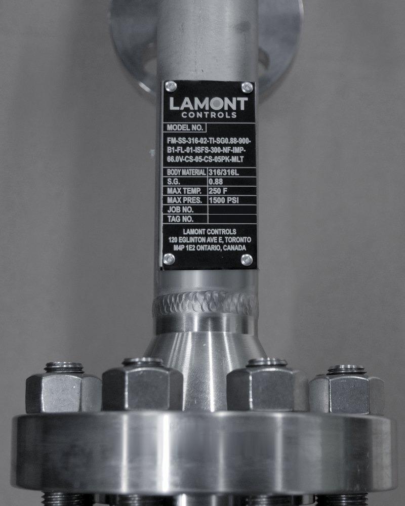
Lamont Controls nameplate with the full model code, on a gauge chamber above a bolted weld-neck flange
On a Lamont gauge the nameplate carries the full model code. On a glass gauge, photograph the maker's plate or tag.
1-833-7LAMONT info@lamontcontrols.com

Glass gauge replacement

A nameplate photo, a datasheet or a drawing can replace the gauge fields: attach it and they become optional. Without a file, enter the centre-to-centre, connection and fluid.

Fields marked * are required. Leave an optional field blank if the value is not known.

Nameplate photos, datasheet or drawing
More about the glass gauge optional
Glass gauge type

Contact

Submissions are reviewed by Lamont Controls Engineering.By sending this form you agree to the Terms of use. See the Privacy policy.

Questions

Glass gauge replacement: frequently asked questions

Is a "magnetic sight glass" the same as a magnetic level gauge?

Yes. The term is in common use, although a magnetic level gauge has no glass in the pressure boundary. A float with a magnet rides on the liquid inside a sealed chamber and turns the flags of an indicator mounted outside it.

Will a magnetic level gauge fit existing glass gauge nozzles?

In most cases, yes. The gauge is built to the existing centre-to-centre, connection size, flange class and facing, in the configuration the vessel already has. The chamber extends below the lower connection to a bottom flange, through which the float is removed, so the space below the gauge must be checked. Fit is confirmed at quotation.

What is needed for a quotation?

Photos of the nameplate and the installed gauge, the centre-to-centre, the connection size and rating, the fluid and its specific gravity at operating temperature, and the operating pressure and temperature. If the nameplate is missing or unreadable, measurements and process data are enough.

Which is safer, a glass gauge or a magnetic level gauge?

A magnetic level gauge has no glass in the pressure boundary: the chamber is welded (Magnamont™, Fortimag™) or bonded (Polysight™), and the indicator, switches and transmitter mount outside it. A glass gauge holds the process with glass and gaskets. For short, cool, low-pressure service, a guarded glass gauge is often acceptable.

Does a magnetic level gauge show the colour of the liquid or foam?

No. It shows the level only. Where operators need to see the liquid itself, such as its colour, clarity or foam, the glass gauge is kept, or both are fitted.

Can a level switch or a transmitter be added later?

Yes. SurePoint™ switches and a LevelSync™ transmitter are externally mounted and magnetically coupled to the same float, with no wetted parts and no additional vessel nozzle. They are fitted at the factory or in the field.

How long can one magnetic level gauge be?

Standard lengths go to 18.5 ft (222 in, 5,640 mm) centre-to-centre in one chamber. Longer lengths are available on request.

To replace a magnetic level gauge of any make, or only its float or indicator, see Retrofits and Spare parts.

Request a quotation Call