Analytics, advertising measurement and session recording stay off unless accepted. They show how the site is used and which advertising brings enquiries. The choice can be changed at any time under Cookie settings at the foot of each page. Privacy policyAnalytics, advertising measurement and session recording stay off unless accepted. They show how the site is used and which advertising brings enquiries. The choice can be changed at any time under Cookie settings at the foot of each page. Privacy policyThis site uses analytics and advertising cookies to show how it is used and which advertising brings enquiries. Decline turns them off. Session recording runs only after Accept. The choice can be changed at any time under Cookie settings at the foot of each page. Privacy policy
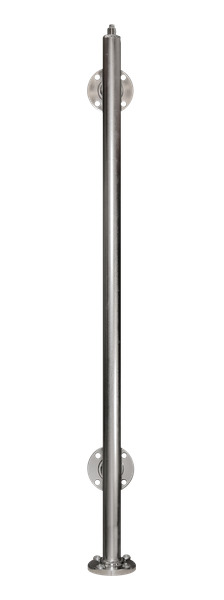
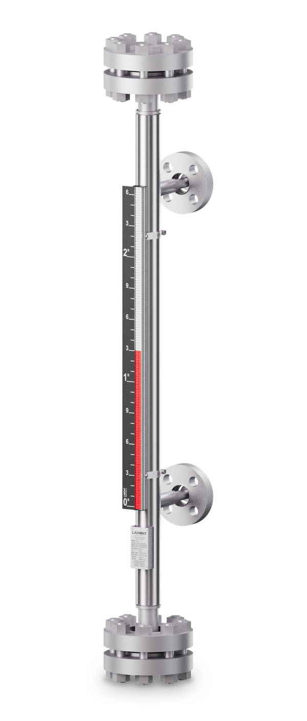
Side–side · flanged connections Weld-neck access flanges, top and bottom
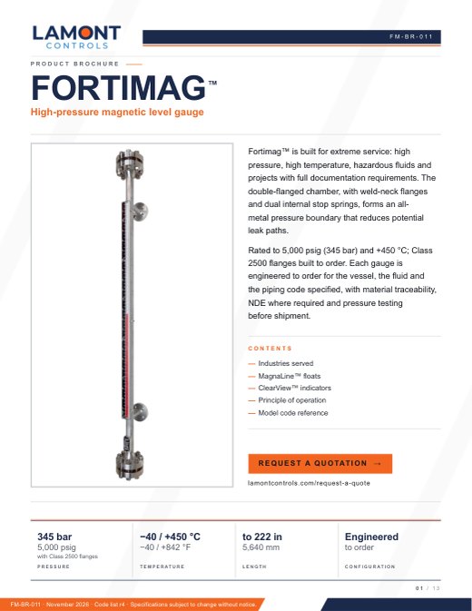
Fortimag™ High-pressure magnetic level gauge
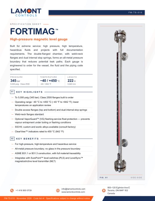
Built for extreme service: high pressure, high temperature, hazardous fluids and projects with full documentation requirements. The double-flanged chamber, with weld-neck flanges and dual internal stop springs, forms an all-metal pressure boundary that reduces potential leak paths. There is no glass in the pressure boundary and no wetted electronics. Each gauge is engineered to order for the vessel, the fluid and the piping code specified, with full material traceability.
Pressure
5,000 psigfull vacuum to 345 bar with Class 2500 flanges
Temperature
−40…+842 °F−40…+450 °C
C-C length, standard to
18.5 ft222 in (5,640 mm)
ANSI flange class, to
Class 1500Class 2500 built to order
Made in Canada
Construction
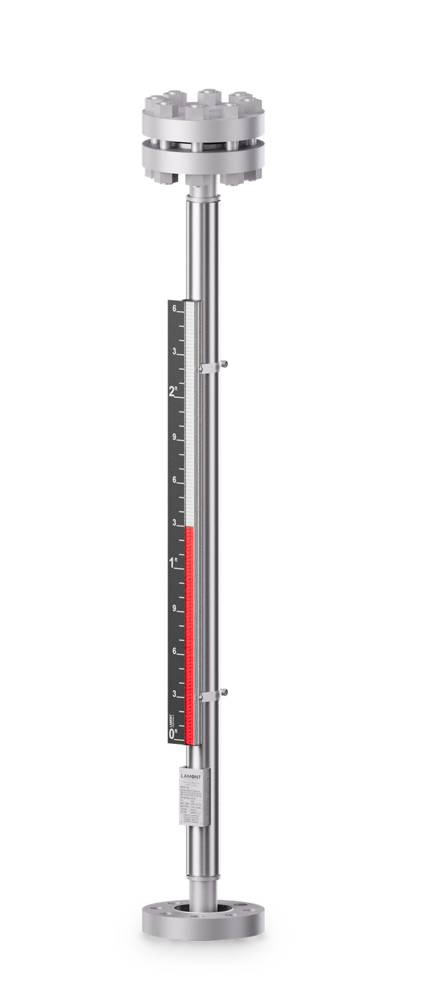
Full-length view
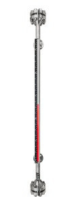
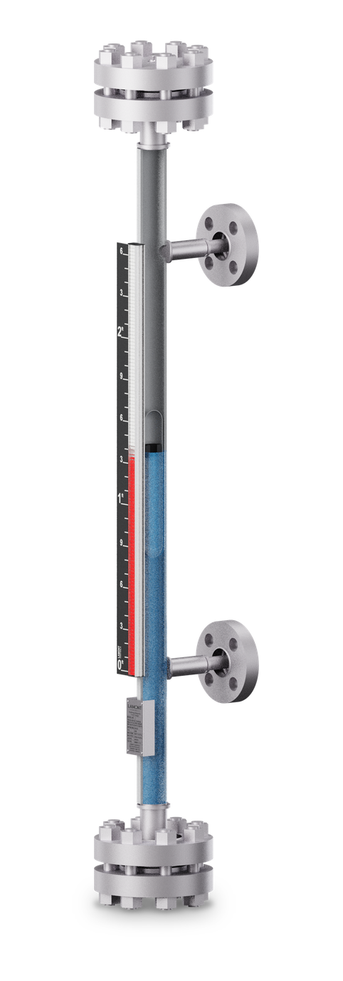
The heavy-duty welded chamber is double-flanged top and bottom with weld-neck flanges. The float travels between dual internal stop springs. The indicator and scale mount outside the chamber and have no contact with the process.
Shown
Side–side configuration
Access flanges
Weld-neck, top and bottom
Connections
Flanged
Indicator
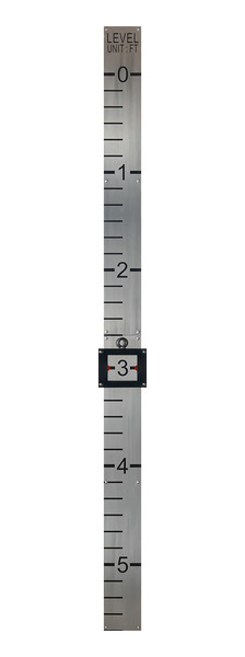
ClearView™ flags, black etched scale in feet and inches
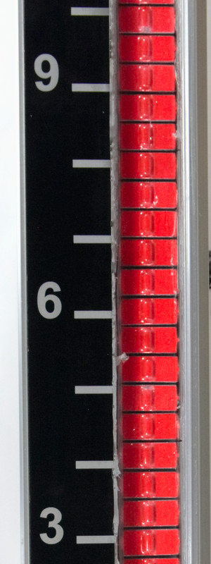
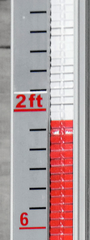
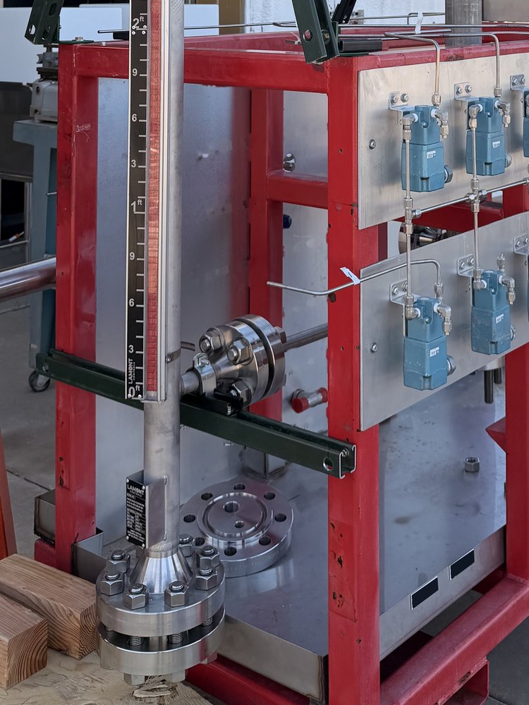
Flanged process connectionBlack etched scale; flags turn red below the levelLamont mark at 0 ft, lower process connectionLamont nameplate with the model code
1Top access flangeWeld-neck, double-flanged and bolted; vent port in the blind flange
2Process connectionsFlanged, threaded or welded; ½ to 4 in
3ScaleEtched aluminum; imperial, metric, percent or volume
4IndicatorClearView™ flags, magnetically coupled to the float
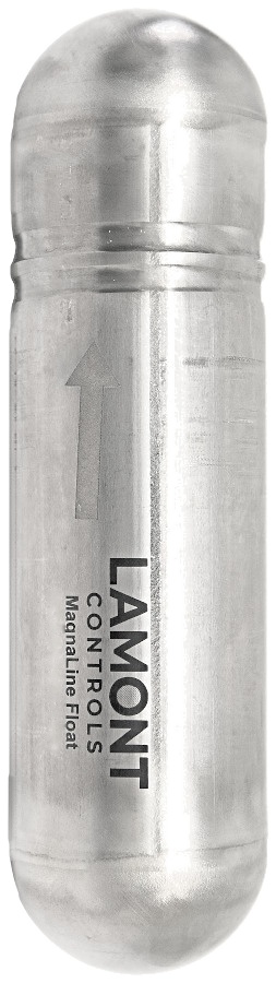
5MagnaLine™ floatTitanium, weighted for the fluid; floats at the liquid level
6ChamberWelded SS316; exotic alloys and linings on request
7Bottom access flangeWeld-neck, double-flanged; drain port per model code
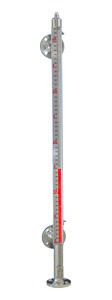
FIG. 02 · Fortimag, side–side, with weld-neck access flanges top and bottom. The float is shown at the liquid level, where the flags change from white to red.
Configurations
Process connection configurations
Renders · dimensions per application5 configurations · renders
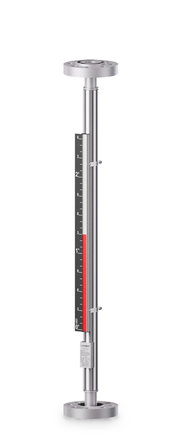
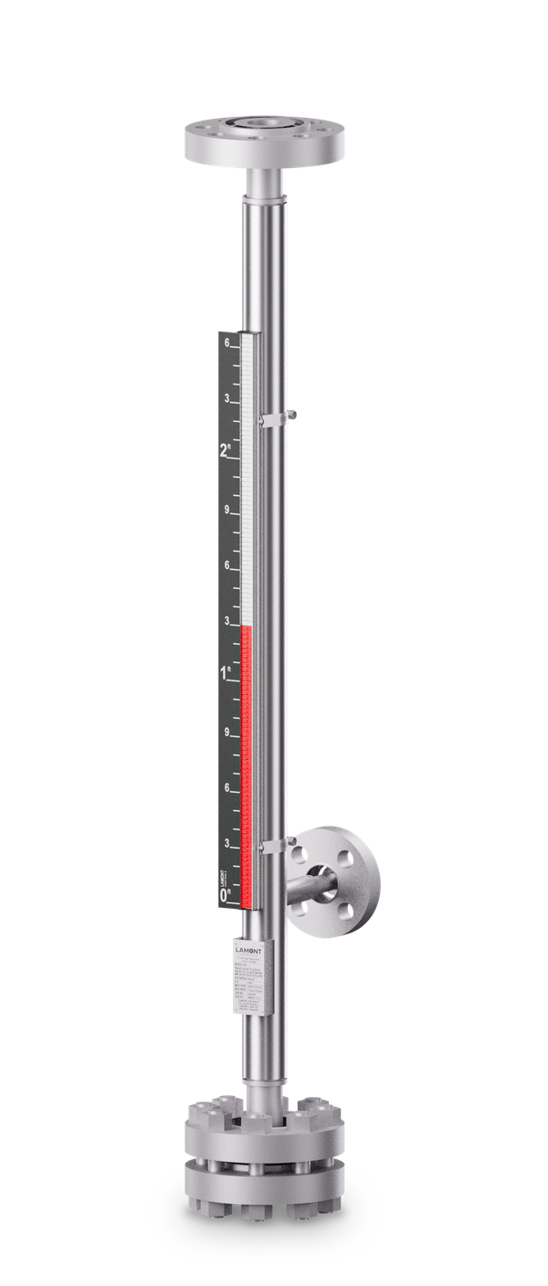
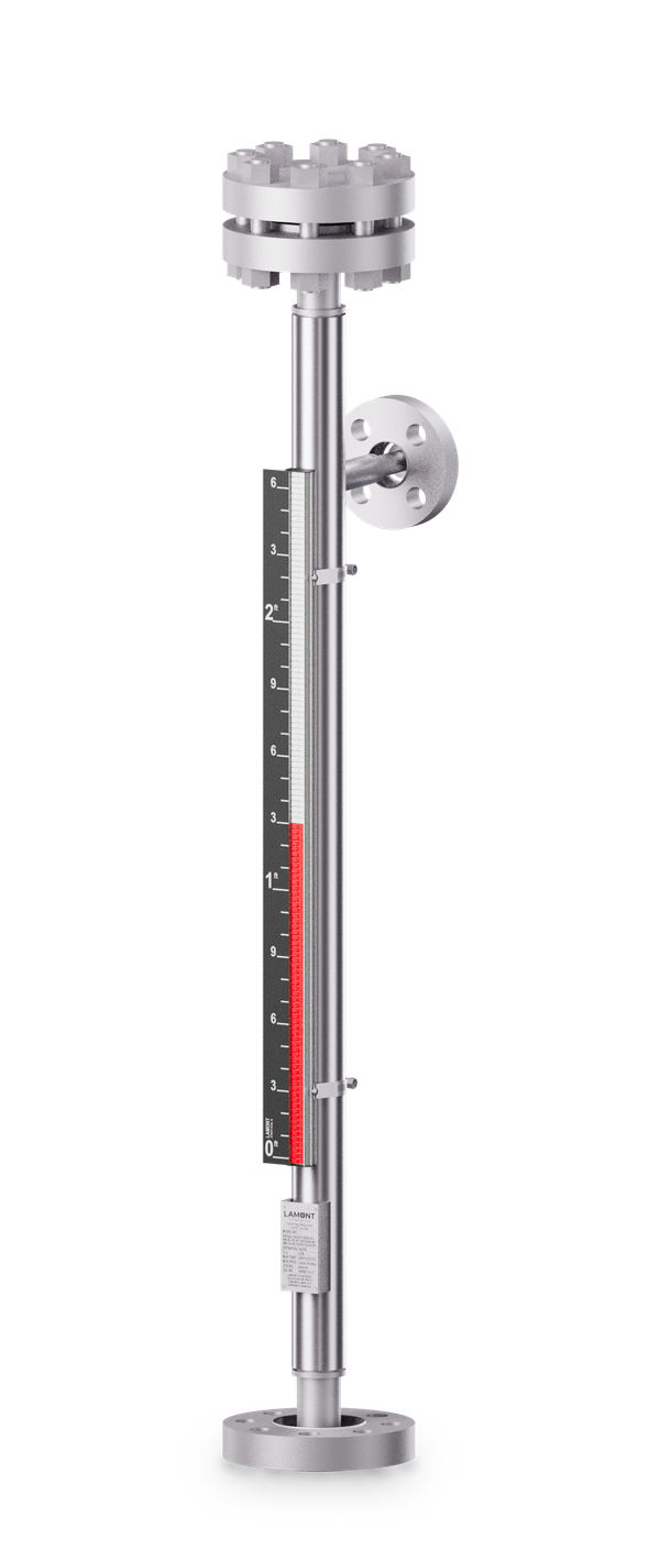
Side–sideStandard. Process connections on the side of the chamber, top and bottom.Top–bottomFlanged process connections on the top and bottom ends of the chamber.Top–sideOne process connection on the top end, one on the side at the bottom.Bottom–sideOne process connection on the bottom end, one on the side at the top.Top-mountChamber and indicator on a single flanged connection on the vessel top.
VaporGuard™ for flashing service. Prevents vapour entrapment under boiling or flashing conditions. Available on Fortimag only.
Piping code construction. Built to ASME B31.1 or B31.3, with full material traceability.
Automation without new nozzles. LevelSync™ and SurePoint™ clamp to the outside of the chamber and can be installed with the vessel in operation.
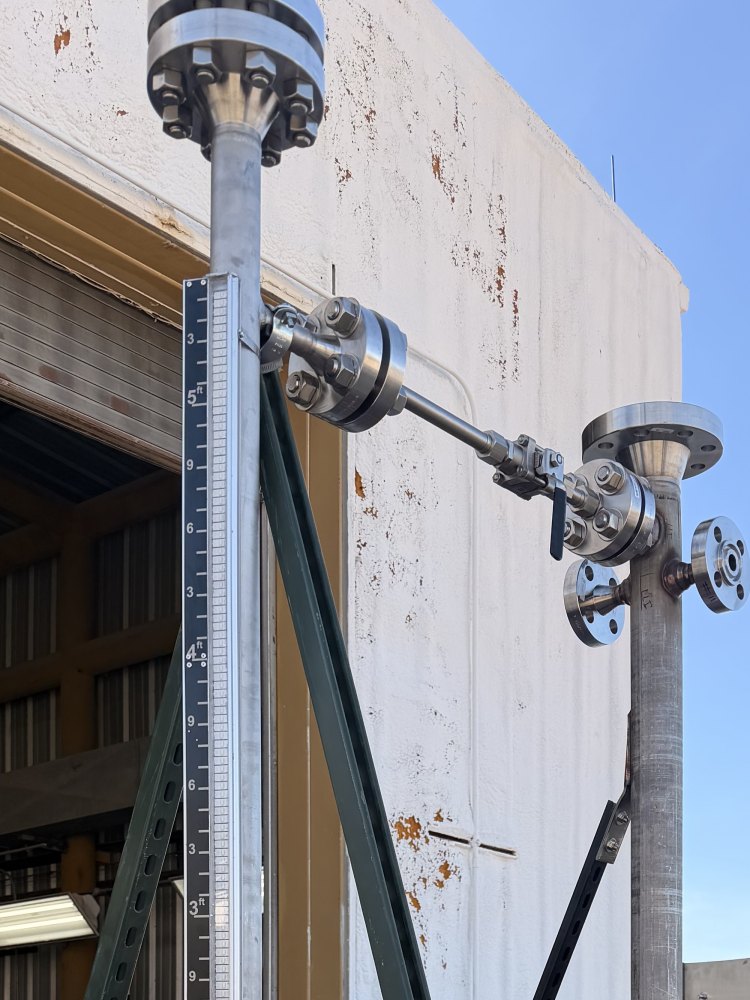
Weld-neck access flange, double-flanged and bolted. The same closure is fitted top and bottom.
Production photographs
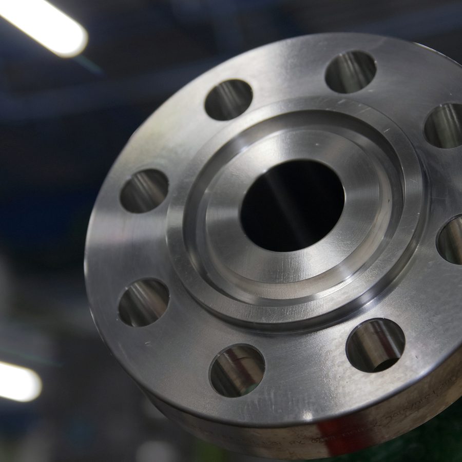
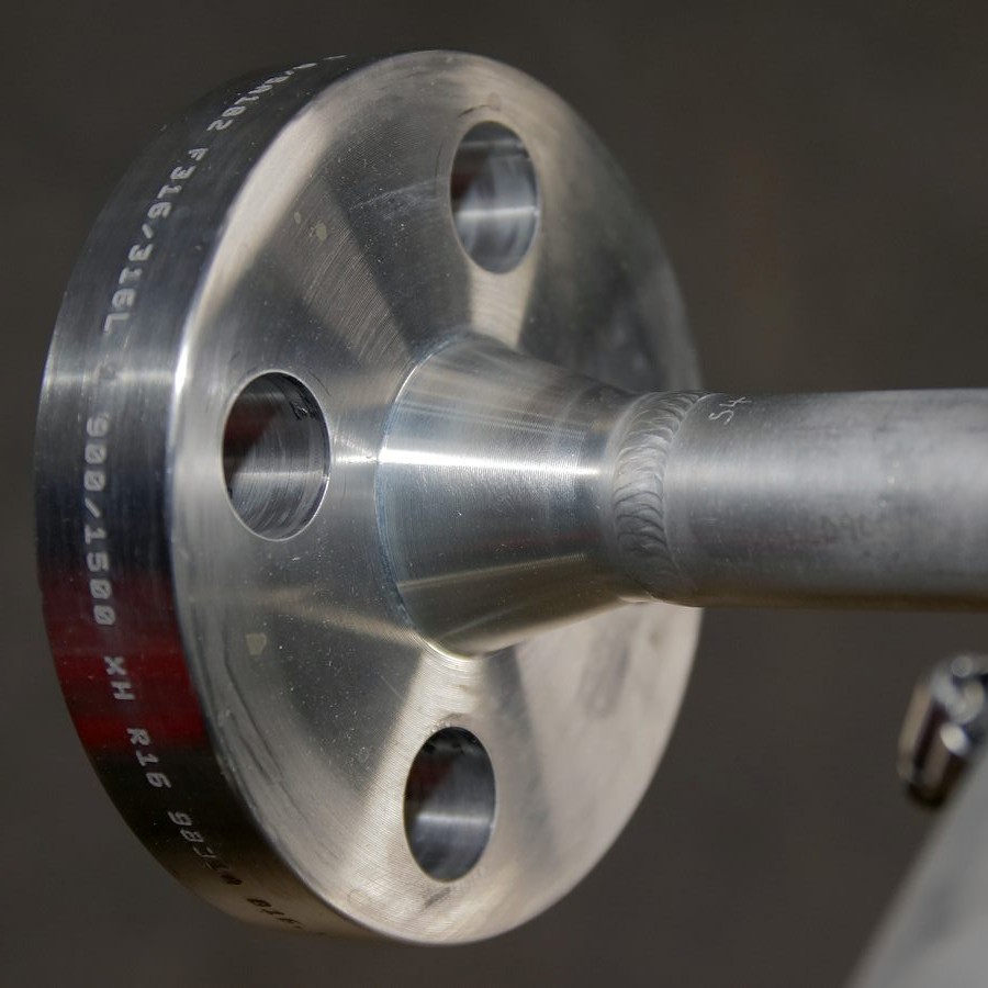
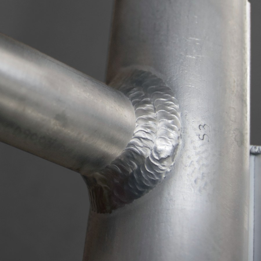
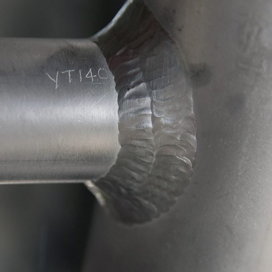
Process flangeForged F316/316L, stamped Class 900/1500 on the rimSide connectionWeld-neck flange on the side nozzleNozzle weldFillet weld at the nozzle-to-chamber jointWeld detailClose-up of the same joint
Operation
Principle of operation
Cutaway · animation to scale · float · magnetic coupling · indication
Cutaway · renderAnimation
Float. A sealed MagnaLine™ float carries a permanent magnetic assembly. The float is weighted for the fluid's specific gravity and floats at the liquid surface. As the level rises or falls, the float moves with it inside the sealed metal chamber.
Magnetic coupling. The float's magnetic field couples through the chamber wall to the ClearView™ indicator mounted outside the chamber. The indicator follows the float and shows the level without contact with the process.
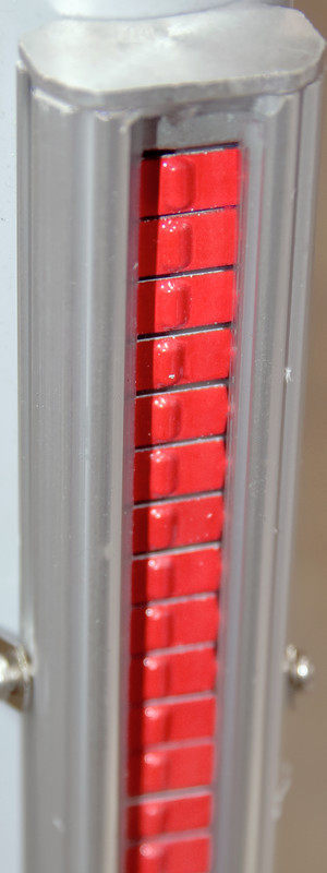
Visual indication. Rotating flags in contrasting colours show liquid below and vapour above. Indication is continuous across the full pressure range and, with the indicator matched to the service temperature, across the full temperature range.
Also available: HS-300. Hermetically sealed, argon-filled indicator in a stainless housing with scale · 572 °F (300 °C). IX: no indicator, for transmitter-only or switch-only service.
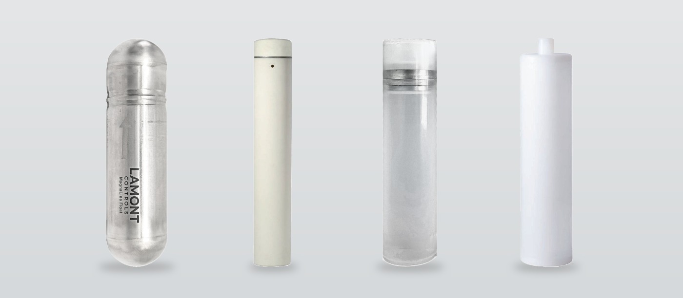
MagnaLine™ floats
TitaniumStandard
Titanium, precision-weighted for the fluid's specific gravity and operating pressure. The standard float for high-pressure, high-temperature service.
316 stainless steelOptional
316/316L stainless steel for heavier fluids and general industrial service.
Ball-segmentEngineered
Spherical geometry resists external collapse, for the highest pressure classes. Titanium or stainless, engineered per application.
Syntactic foamEngineered
Solid buoyant core with no internal cavity to collapse, for extreme-pressure service. Moderate-temperature service.
Coated, lined, exotic-alloy and specialty floats are engineered to order; consult factory. Minimum SG 0.34, subject to float design and application conditions.
Automation
LevelSync™ transmitters and SurePoint™ switches
LevelSync™ · SurePoint™
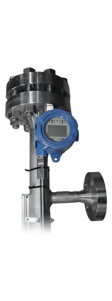
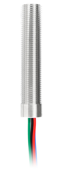
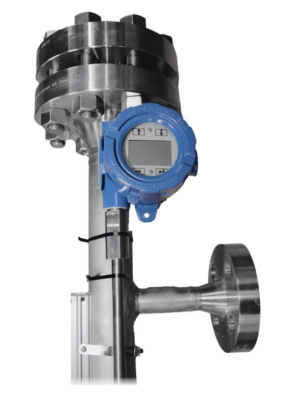
LevelSync™ transmitters and SurePoint™ switches are externally mounted and magnetically coupled to the gauge’s MagnaLine™ float. They have no wetted parts, require no additional vessel nozzle, and are fitted at the factory or in the field.
LevelSync™
Magnetostrictive level transmitter
Continuous level output from the gauge float by magnetostrictive time-of-flight sensing. No moving parts and no routine recalibration.
Output
4–20 mA with HART®; Modbus RTU or DDA optional
Accuracy
±0.039 in (±1 mm) inherent
Length
12 to 144 in (305 to 3,658 mm); longer on request
Process temp.
To 302 °F (150 °C); to 527 °F (275 °C) with thermal standoff
Hazardous area
Intrinsically safe or explosionproof; FM, FMc, ATEX, IECEx, UKCA
Housing
Epoxy-coated aluminum or 316L stainless; NEMA 4X, IP65
Order with option MLT in the gauge model code.
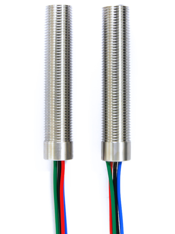
SurePoint™
Magnetic point-level switch
Leverless switch actuated by the float's magnet for high and low level alarms and basic control. No moving levers and no actuation power.
Contact
SPDT, latching
Rating
Up to 25 W resistive; 1 A at 24 VDC; 150 VDC · 230 VAC max
Hazardous area
Class I, Div. 1 (UL 1203); Class II, Groups E, F, G; gas groups confirmed at quotation
Switch temp.
−58 to +221 °F (−50 to +105 °C)
Housing
300-series stainless steel, factory sealed
Mounting
Band clamp; set point adjustable along the chamber
Temperature. Fortimag service temperatures can exceed the limits of both devices. LevelSync™: process temperature to 302 °F with standard mounting and 302–527 °F with thermal standoff; consult factory above 527 °F. SurePoint™: operating temperature −58 to +221 °F (−50 to +105 °C).
Hazardous-area certifications are held by Lamont's component manufacturing partner and apply to the supplied product. Final certification, temperature class and marking depend on configuration and are confirmed at quotation.
Data
Technical specifications
Ratings
Pressure
Full vacuum to 5,000 psig (345 bar); Class 2500 flanges built to order
Temperature
−40 to +842 °F (−40 to +450 °C); lower temperatures on application review
Measuring range
Standard lengths to 18.5 ft (222 in, 5,640 mm) centre-to-centre; longer lengths on request
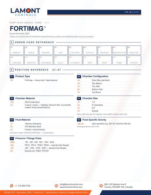
Passivated per ASTM A380 / A967 (standard) · electropolished, external surfaces, per ASTM B912 · painted · powder coated
Connections
Process connections
Flanged; threaded (FNPT / MNPT); welded (Weldolet, Sockolet). ½ to 4 in NPS; DN15 to DN65; 15A to 50A
Flange classes
ANSI 150, 300, 600, 900, 1500 and 2500 (Class 2500 built to order) · DIN PN10 / 16 / 25 / 40 · JIS 5K to 20K (DIN and JIS special order) · other classes on request
Vent and drain
Threaded ⅛ to 1 in; flanged ½ to 1 in; custom machined ports; or none
Indication
Scales
Feet and inches · metres / cm · percent · gallons or litres to tank volume · custom · none
Scale material
Etched aluminum, resistant to UV, abrasion and chemical attack; marking to MIL-STD-130N. Non-metallic scales optional
Codes, testing and documentation
Construction code
Industrial grade (IG), ASME B31.1 (B1) or ASME B31.3 (B3), specified in the model code
Pressure test
Pressure tested before shipment; hydrostatic test at not less than 1.5 × design pressure where specified; test reports available
Material traceability
Maintained throughout manufacturing; MTRs available
NDE
Per the governing code where required: visual examination of welds and final assembly, dye-penetrant examination of fillet welds, radiographic (X-ray) or ultrasonic examination of full-penetration butt welds, and positive material identification (PMI) where specified
Prevents vapour entrapment under boiling or flashing conditions. Fortimag only.
FloatSense™ float-integrity monitoring (FS)
A clear visual signal at the indicator if the float loses buoyancy and sinks, so a failed float is not read as a low level.
Insulation blanket (IB)
Wraps the chamber; a clear window keeps the indicator readable.
Heat tracing (HT)
Freeze protection for cold-climate service.
Interface service (INT)
Float set for the second liquid's SG, specified in the model code.
Custom options (X)
Special accessories engineered to the application, on request.
Ratings. Pressure and temperature ratings depend on materials, connections and configuration, and are confirmed at quotation.
Custom configurations. Non-standard lengths, exotic alloys and special process connections on request. Contact Lamont Controls Engineering.
Quality
Quality, testing and documentation
Build and test sequence · documents
01
Approval drawing
Issued after the purchase order. The design is confirmed on the drawing before fabrication starts.
02
Material
Material traceability is maintained throughout manufacturing.
03
Construction code
Industrial grade, ASME B31.1 or ASME B31.3, as specified in the model code.
04
NDE
Per the governing code where required: visual examination of welds and final assembly, dye-penetrant examination of fillet welds, radiographic (X-ray) or ultrasonic examination of full-penetration butt welds, and positive material identification (PMI) where specified.
05
Pressure test
Pressure tested before shipment; hydrostatic test at not less than 1.5 × design pressure where specified.
06
Float and indicator
The float is precision-weighted for the fluid’s specific gravity and operating pressure. The indicator and scale mount outside the chamber.
Documents
Material test reports (MTRs)
Available
Hydrostatic test reports
Available
Approval drawing
Issued after the purchase order
Certificate of origin
Chamber-of-commerce certified, on request
Further inspection
Available on request
Quotation
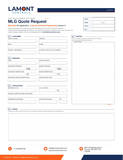
Request a quotation
Complete the process conditions below, or attach a datasheet or drawing. Fields marked * are required. Process data speeds up the quotation.
For a general enquiry, select Quick message and provide your contact details with a brief note.
For a replacement, attach a photo of the existing nameplate and enter the centre-to-centre dimension.
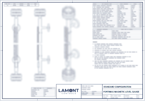
LAMONT CONTROLS ENGINEERING · SENT AFTER REVIEWDimensional drawingsOutline drawings for the standard Fortimag™ configurations, one sheet each: side–side, top–bottom, top–side, bottom–side and top-mount. Sent by Lamont Controls Engineering after review; final dimensions are on the approval drawing, issued after the purchase order.
Class 900 gauge with weld-neck flanges for storable propellant service on a propulsion test skid. Built to ASME B31.1 with 100% radiography of butt welds and fitted with a LevelSync™ transmitter.
Fortimag™ · LevelSync™ · ASME B31.1
Applications
Industries served
12 industries
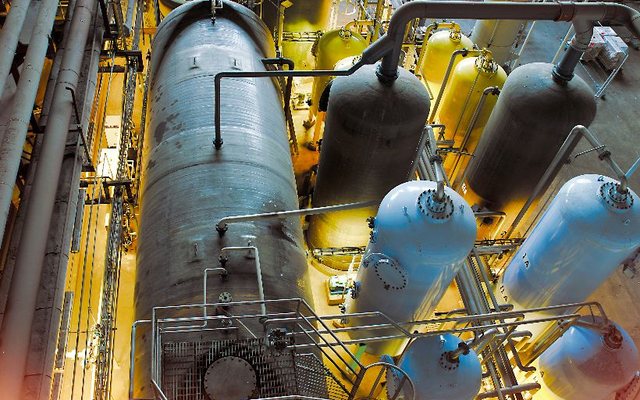
Aerospace and propulsion test
Propellant run tanks, thrust-chamber coolant and high-pressure test-cell systems on engine test stands.
Storable propellants
Fuels and oxidizers in storage and fuelling systems, with a sealed metal chamber.
Hydrogen and energy transition
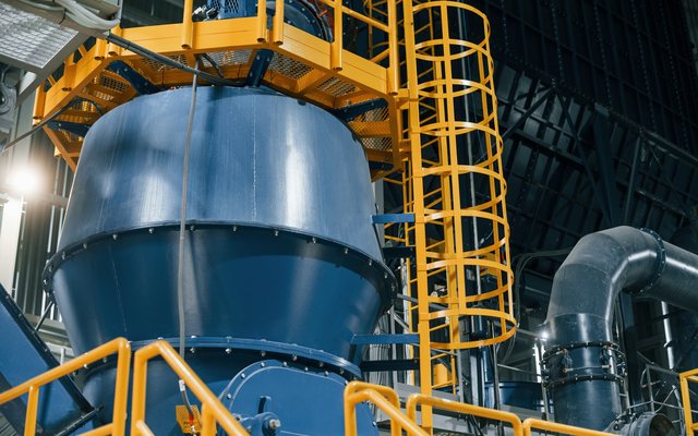
Liquid-level service in hydrogen plants: electrolyzer gas–liquid separators, KOH and water tanks, compressor knock-out drums and condensate pots.
Mineral processing and autoclaves
Pressure-oxidation autoclaves and acid-leach circuits, with exotic-alloy construction on application review.
Boiler drums and steam generators
High-pressure drum level and HRSG service, with VaporGuard™ for flashing conditions.
Nuclear power
High-pressure balance-of-plant feedwater and auxiliary systems in non-safety-related service, with material traceability maintained throughout manufacturing.
High-pressure separators and recycle-gas knock-out drums in hydrocracker and hydrotreater units, in H₂ / H₂S service.
High-pressure reactors and synthesis loops
Separators and liquid inventory vessels in hydrogenation, ammonia, urea and methanol service.
Offshore and HP/HT upstream
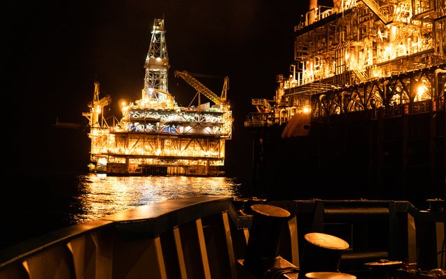
High-pressure, high-temperature separators and test packages requiring rated, traceable construction.
Defence, research and national labs
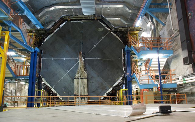
High-pressure test loops and specialty fuels, built to project specification.
Also serving chlor-alkali and exotic corrosives · geothermal wells · pulp and paper digesters. For standard industrial service, see Magnamont™; for aggressive corrosives, see Polysight™.