Lamont Controls 1-833-7LAMONT Request a quotation Call

Cookies on this site

Analytics, advertising measurement and session recording stay off unless accepted. They show how the site is used and which advertising brings enquiries. The choice can be changed at any time under Cookie settings at the foot of each page. Privacy policy

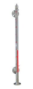
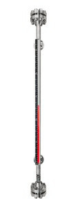
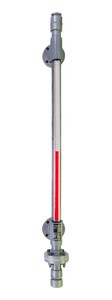
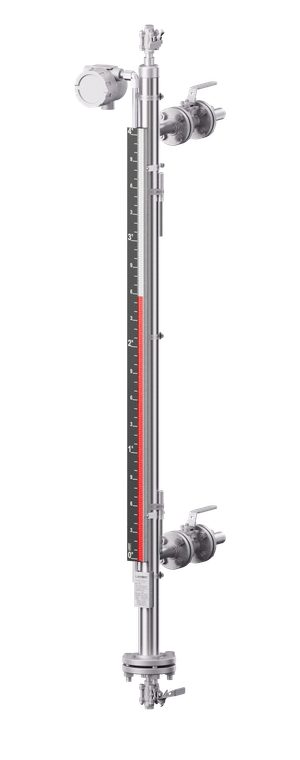
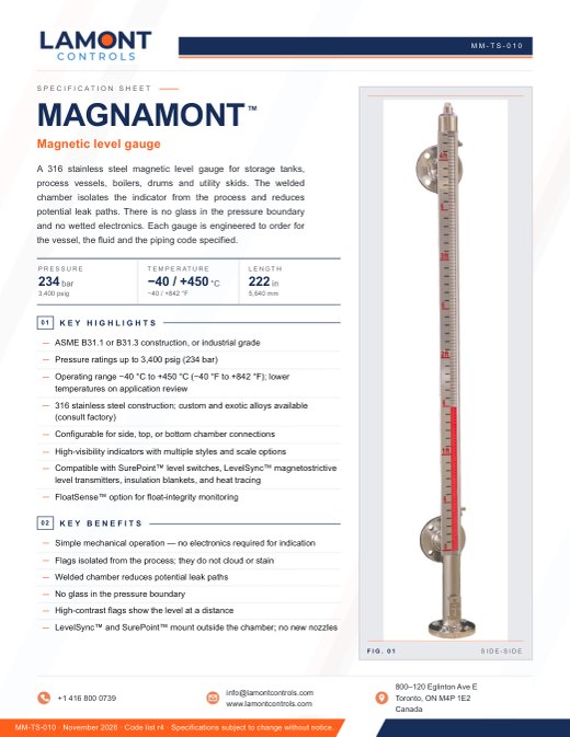
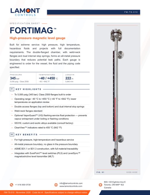
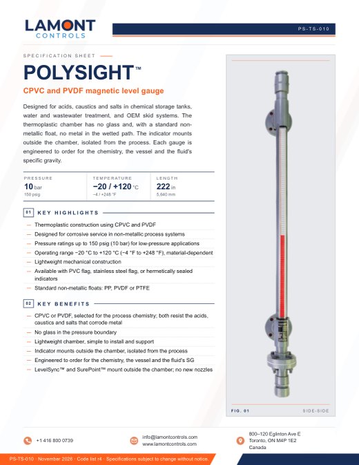
Magnamont magnetic level gauge, full length: side–side with Weldolet connections, black etched scale and red and white flags Fortimag magnetic level gauge, full length: weld-neck access flanges top and bottom, black etched scale and red and white flags Polysight magnetic level gauge, full length: grey CPVC chamber, flanged connections and a transparent PVC flag indicator
Magnamont™ · Fortimag™ · Polysight™
Side–side configuration

Magnetic level gauges Engineered to order in stainless steel and thermoplastic

A magnetic level gauge, also called a magnetic level indicator (MLI), shows the liquid level in a vessel on a column of flags mounted outside a sealed chamber. A float carrying a permanent magnet rides on the liquid inside the chamber and turns each flag as it passes. The level is readable at a distance, with no glass in the pressure boundary and no wetted electronics. Lamont Controls builds side- and top-mounted gauges, each engineered to the vessel, the fluid and the piping code on the order: Magnamont™ in 316 stainless steel for industrial service, Fortimag™ for extreme pressure and temperature, and Polysight™ in CPVC or PVDF for corrosive chemistry. LevelSync™ transmitters and SurePoint™ switches fit all three.

Full vacuum to the pressure shown · Made in Canada

Comparison

Magnamont™, Fortimag™ and Polysight™ compared

All three gauges operate on the same principle. They share five chamber configurations (side–side, top–bottom, top–side, bottom–side and top-mount), the same standard length and the same LevelSync™ transmitter and SurePoint™ switch options. The gauges differ in the chamber: its material, its construction, and its pressure and temperature ratings.

Magnamont, Fortimag and Polysight magnetic level gauges compared
Magnamont™SS316 magnetic level gauge Fortimag™Extreme-service magnetic level gauge Polysight™Thermoplastic magnetic level gauge
Chamber material316 stainless steel (SS316) standard; Hastelloy, Monel K-500, Inconel 625, coated or lined: consult factory316 stainless steel (SS316) standard; Hastelloy, Monel K-500, Inconel 625, coated or lined: consult factoryCPVC (standard) or PVDF; custom or exotic: consult factory
Chamber constructionWelded chamber, slip-on process flanges, internal float stop spring; 1.5 or 2 inDouble-flanged top and bottom, weld-neck flanges, dual internal stop springs; 1.5 or 2 in, 2.5 in for Class 1500Thermoplastic chamber, solvent- and fusion-bonded joints; 2 in
Pressure3,400 psigfull vacuum to 234 bar5,000 psigfull vacuum to 345 bar150 psigfull vacuum to 10 bar
Temperature−40 to +842 °F (−40 to +450 °C); lower temperatures on application review−40 to +842 °F (−40 to +450 °C); lower temperatures on application review−4 to +248 °F (−20 to +120 °C); CPVC chamber to about 199 °F (93 °C), PVDF to about 248 °F (120 °C)
Standard lengthTo 18.5 ft (222 in, 5,640 mm) centre-to-centre; longer on requestTo 18.5 ft (222 in, 5,640 mm) centre-to-centre; longer on requestTo 18.5 ft (222 in, 5,640 mm) centre-to-centre; longer on request
Process connectionsFlanged, threaded (FNPT / MNPT) or welded (Weldolet, Sockolet); ½ to 4 inFlanged, threaded (FNPT / MNPT) or welded (Weldolet, Sockolet); ½ to 4 inFlanged or threaded (FNPT / MNPT); 1, 1½ or 2 in (standard 2 in); 3 in: consult factory
Flange classesANSI 150 to 1500; DIN and JIS special orderANSI 150 to 2500 (Class 2500 built to order); DIN and JIS special orderANSI 150 (standard); DIN PN10 and JIS 5K on request
Minimum SG0.34consult factory below 0.450.340.59
FloatsTitanium (standard) or 316 stainless steel; engineered floats: consult factoryTitanium (standard) or 316 stainless steel; ball-segment and syntactic foam, engineered per applicationPTFE or PVDF (standard, by chamber) or polypropylene; custom: consult factory
IndicatorsClearView™ ISFS-300 (standard), ISF-300, IAF-450, HS-300ClearView™ ISFS-300 (standard), ISF-300, IAF-450, HS-300ClearView™ IPVC-80 (standard), IPVC-120, ISFS-300, HS-80
Construction and testingASME B31.1 or B31.3, or industrial grade; pressure tested before shipment, hydrostatic at not less than 1.5 × design pressure where specified; MTRs and test reports availableIndustrial grade, ASME B31.1 or B31.3; pressure tested before shipment, hydrostatic at not less than 1.5 × design pressure where specified; radiographic (X-ray) or ultrasonic examination where specified; MTRs and test reports availableIndustrial grade thermoplastic; pressure tested before shipment, hydrostatic at not less than 1.5 × design pressure and 24-hour water-fill leak test where specified; test certificates available
OptionsFloatSense™, insulation blanket, heat tracing, interface serviceVaporGuard™ for flashing service (Fortimag only), FloatSense™, insulation blanket, heat tracing, interface serviceFloatSense™, interface service
Typical serviceStorage tanks, process vessels, boilers, drums and utility skidsHigh-pressure separators and gas processing, HP feedwater and deaerators, hydrogen, propellant and test systemsAcids, caustics and salts in chemical storage, water and wastewater treatment, and OEM skids
Magnamont™Fortimag™Polysight™
  • Ratings. Pressure and temperature ratings depend on materials, connections and configuration, and are confirmed at quotation.
  • External devices. The indicator, LevelSync™ and SurePoint™ mount outside the chamber. Their temperature ratings apply to the device, not to the process.

Operation

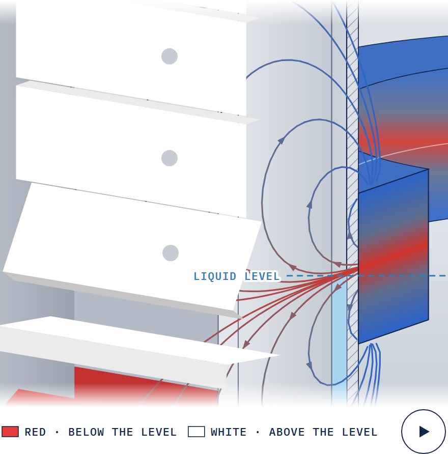
Principle of operation

Magnamont™ shown · the same principle on all three gauges
  1. Float. A sealed MagnaLine™ float carries a permanent magnetic assembly and is weighted to the fluid's specific gravity. As the level rises or falls, the float moves with it inside the chamber.
  2. Magnetic coupling. The float's field couples through the chamber wall to the ClearView™ indicator outside. The indicator follows the float and shows the true level without contact with the process.
  3. Visual indication. The indicator is a column of flags in contrasting colours. Each flag turns as the float passes, so the column shows liquid below and vapour above. The reading is continuous and needs no power.

How a magnetic level gauge works: full principle of operation

Automation

LevelSync™ transmitters and SurePoint™ switches

Options on all three gauges

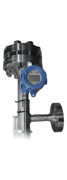
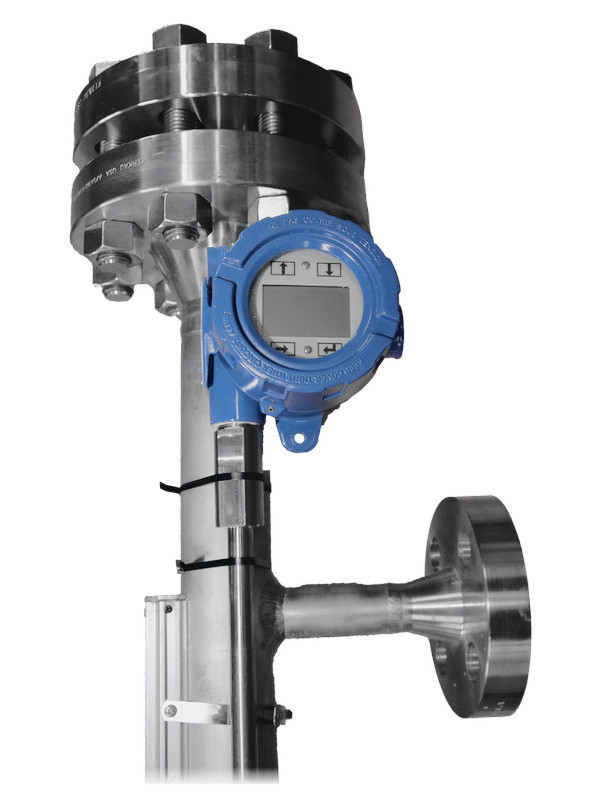
The transmitter and the switches are externally mounted and magnetically coupled to the same MagnaLine™ float as the indicator. They have no wetted parts, require no additional vessel nozzle, and are fitted at the factory or in the field.

LevelSync™

Magnetostrictive level transmitter

Continuous level output from the gauge float by magnetostrictive time-of-flight sensing. No moving parts and no routine recalibration.

Output
4–20 mA with HART®; Modbus RTU or DDA optional
Accuracy
±0.039 in (±1 mm) inherent
Hazardous area
Intrinsically safe or explosionproof; FM, FMc, ATEX, IECEx, UKCA
Housing
Epoxy-coated aluminum or 316L stainless; NEMA 4X, IP65

Order with option MLT in the gauge model code.

LevelSync™ specifications

SurePoint™

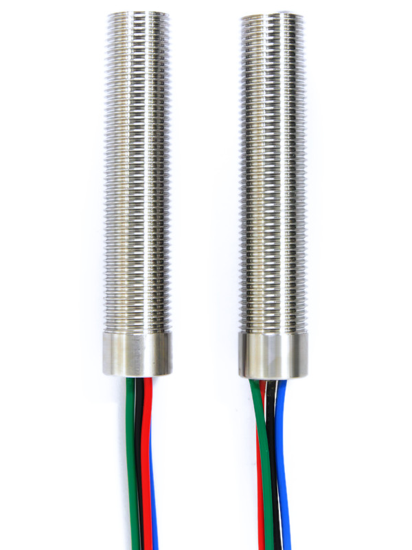
Magnetic point-level switch

Leverless SPDT switch actuated by the float's magnet, for high and low level alarms and basic control. The set point is the clamp position on the chamber.

Contact
SPDT, latching; up to 25 W resistive, 1 A at 24 VDC, 150 VDC · 230 VAC max
Hazardous area
Class I, Div. 1 explosionproof, per UL 1203
Switch temp.
−58 to +221 °F (−50 to +105 °C), outside the chamber
Housing
300-series stainless steel, factory sealed

Order 1 to 8 switches with option PLS-1 to PLS-8.

SurePoint™ specifications

Hazardous-area certifications are held by Lamont's component manufacturing partner and apply to the supplied product. Final certification, temperature class and marking depend on configuration and are confirmed at quotation.

Level bridles and chambers

Level bridles and external chambers

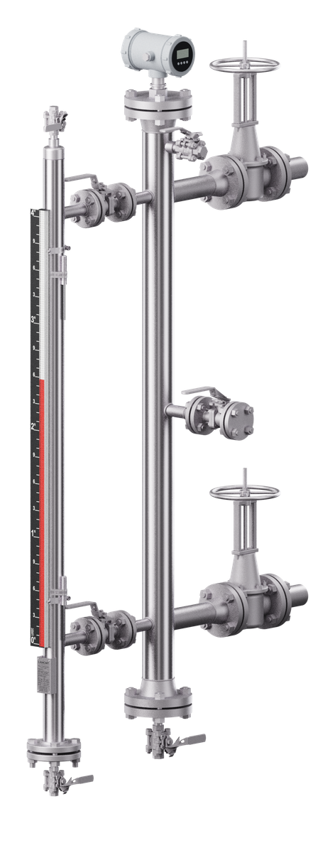
A level bridle connects every level instrument on a vessel to one shared liquid column through one pair of vessel nozzles. The magnetic level gauge, transmitter and switches mount on the bridle, so none requires its own vessel penetration. Isolation valves allow the instruments to be serviced without draining the vessel.

  • Level package. In 316 stainless steel, the bridle can also serve as the gauge chamber: one standpipe carries a Magnamont™ gauge, a LevelSync™ transmitter and SurePoint™ switches.
  • Construction. The same as the gauge chambers: 316 stainless steel, built to ASME B31.3 or B31.1 and pressure tested before shipment. The approval drawing is issued after the purchase order.
  • External chambers. A chamber houses one instrument, such as a guided wave radar probe; a bridle carries several on one standpipe.
Render of an instrument bridle: a 3-inch stainless standpipe with a guided-wave radar on the top flange, a Magnamont magnetic level gauge on its own valved connections with SPDT clamp-on switches, a valved spare connection with a blind flange, ¾" valved vent and drain, and a gate valve bolted to each vessel nozzle.
Render · instrument bridle
Render of a Magnamont™ level package: the gauge chamber serves as the bridle, with a LevelSync™ transmitter at the top, SPDT clamp-on switches, an isolation valve on each vessel nozzle, and a valved vent and drain.
Render · level package: bridle as a Magnamont™ chamber

Applications

Selected projects

Customer names withheld

Quality

Quality, testing and documentation

Each gauge line is built and tested to its own technical specification sheet. The design for an order is confirmed on the approval drawing, issued after the purchase order, before fabrication starts.

Build and test sequence · welded chambers, Magnamont™ and Fortimag™

  1. 01

    Approval drawing

    Issued after the purchase order. The design is confirmed on it before fabrication starts.

  2. 02

    Material

    Material traceability is maintained throughout manufacturing.

  3. 03

    Construction code

    Built to ASME B31.1 or ASME B31.3, or industrial grade, as specified in the model code.

  4. 04

    NDE

    Per the governing code where required: visual examination, dye-penetrant examination of fillet welds, radiographic (X-ray) or ultrasonic examination of full-penetration butt welds (Fortimag™), and positive material identification (PMI) where specified.

  5. 05

    Pressure test

    Pressure tested before shipment; hydrostatic test at not less than 1.5 × design pressure where specified.

  6. 06

    Float and indicator

    The float is weighted to the fluid’s specific gravity. The indicator and scale mount outside the chamber.

Polysight™: visual inspection of solvent- and fusion-bonded joints and the assembly, a pressure test before shipment and, where specified, a hydrostatic test with clean water at not less than 1.5 × design pressure (1 hour minimum), then a 24-hour water-fill leak test. Test certificates available.

Documents

MTRs and hydrostatic test reports
Available · Magnamont™ and Fortimag™
Test certificates
Available · Polysight™
Approval drawing
Issued after the purchase order
Certificate of origin
Chamber-of-commerce certified, on request
Further inspection
Available on request, where applicable

Codes, testing and documentation for each gauge line are compared on About Lamont Controls. Pressure and temperature ratings depend on materials, connections and configuration, and are confirmed at quotation.

Downloads

Documentation

Documents by line

Each gauge line has a product brochure, a technical specification sheet and a model code reference. The documents are available from the documentation section of each line's page; a business email address is required.

The fillable quote request form is available to all visitors. Outline drawings for the standard configurations, one sheet each, are sent by Lamont Controls Engineering after review. Final dimensions are given on the approval drawing, issued after the purchase order.

Cover of MM-TS-010, Magnamont technical specification sheet, November 2026MM-TS-010 · NOVEMBER 2026Magnamont™ technical specification sheet2 pages · 314 KB PDFMagnamont™ documents
Cover of FM-TS-010, Fortimag technical specification sheet, November 2026FM-TS-010 · NOVEMBER 2026Fortimag™ technical specification sheet2 pages · 309 KB PDFFortimag™ documents
Cover of PS-TS-010, Polysight technical specification sheet, November 2026PS-TS-010 · NOVEMBER 2026Polysight™ technical specification sheet2 pages · 302 KB PDFPolysight™ documents
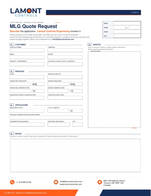
Cover of LC-QR-010, the fillable MLG quote request formLC-QR-010 · NOVEMBER 2026Quote request form1 page · 82 KB · fillable PDFDownload

Guides. How to specify a magnetic level gauge · Installation best practices · Troubleshooting

Quotation

Request a quotation

Send the process conditions, or attach a datasheet, drawing or nameplate photo. Lamont Controls Engineering reviews the conditions, recommends the line and replies within 1 to 3 business days with a quotation.

Alternatively, complete the fillable quote request form (PDF) and return it by email.

1-833-7LAMONT info@lamontcontrols.com

What to include

  • Fluid and specific gravity
  • Operating and design pressure and temperature
  • Centre-to-centre distance
  • Process connection size and rating
  • Quantity and tag numbers

Questions

Frequently asked questions

What is a magnetic level gauge?

A magnetic level gauge, or magnetic liquid level gauge, is a sealed chamber connected to the vessel. A float inside the chamber rides on the liquid at the vessel's level. A permanent magnet in the float turns a column of flags mounted outside the chamber: one colour below the level, the other above it. The reading needs no power, and no glass or electronics are in contact with the process. A transmitter and switches can read the same float from outside the chamber.

Is a magnetic level indicator the same as a magnetic level gauge?

Yes. Magnetic level indicator (MLI), magnetic float level gauge, bypass level indicator and mag gauge are names for the same instrument: a float with a magnet inside a chamber, driving an indicator outside it. Lamont Controls calls its Magnamont™, Fortimag™ and Polysight™ lines magnetic level gauges.

How do Magnamont, Fortimag and Polysight differ?

All three operate on the same principle and differ in the chamber. Magnamont™ in 316 stainless steel covers most industrial service, from full vacuum to 3,400 psig (234 bar) and −40 to +842 °F (−40 to +450 °C). Fortimag™ is rated for the highest pressures, to 5,000 psig (345 bar), in a double-flanged chamber with weld-neck flanges, and is the only gauge with VaporGuard™ for flashing service. Polysight™, in CPVC or PVDF, handles acids, caustics and salts, to 150 psig (10 bar) and +248 °F (+120 °C). The selection guide on this page marks the gauges that fit the conditions entered; ratings are confirmed at quotation.

Can a transmitter or alarm switches be added?

Yes, on all three gauges. A LevelSync™ magnetostrictive transmitter provides a 4–20 mA signal with HART® (option MLT), and 1 to 8 SurePoint™ SPDT switches provide high and low level alarms (options PLS-1 to PLS-8). The transmitter and the switches are externally mounted and magnetically coupled to the same float, with no wetted parts and no additional vessel nozzle, and are fitted at the factory or in the field.

Can Lamont replace an installed gauge or a sight glass?

Yes. A replacement Magnamont™, Fortimag™ or Polysight™ is built to the centre-to-centre distance and process connections of the existing gauge, for Lamont gauges and other makes, with the chamber material, float and indicator selected for the fluid and the operating conditions. Where a sight glass is in service, a Magnamont™ replaces the glass assembly with a welded, all-metal chamber on standard process connections. Floats, indicators and scales are also supplied for gauges already in service. Include a photo of the nameplate with the request. See Retrofits and Replace a glass level gauge.

What testing and documentation are supplied?

Magnamont™ and Fortimag™ chambers are built to ASME B31.1 Power Piping or ASME B31.3 Process Piping, or industrial grade, and are pressure tested before shipment, with a hydrostatic test at not less than 1.5 × design pressure where the order specifies it. Material traceability is maintained throughout manufacturing; MTRs and hydrostatic test reports are available. Polysight™ chambers are pressure tested before shipment, with a hydrostatic test at not less than 1.5 × design pressure and a 24-hour water-fill leak test where the order specifies them; test certificates are available. The approval drawing is issued after the purchase order.

What information is needed for a quotation?

A quotation requires the fluid and its specific gravity, the operating and design pressure and temperature, the centre-to-centre distance, the process connection size and rating, and the quantity. A datasheet, drawing or nameplate photo can be attached instead, and several tags can be listed in one request. Submit the request through the quotation form or send it to info@lamontcontrols.com; the fillable quote request form (LC-QR-010) is also accepted by email.

Request a quotation Call