Analytics, advertising measurement and session recording stay off unless accepted. They show how the site is used and which advertising brings enquiries. The choice can be changed at any time under Cookie settings at the foot of each page. Privacy policyAnalytics, advertising measurement and session recording stay off unless accepted. They show how the site is used and which advertising brings enquiries. The choice can be changed at any time under Cookie settings at the foot of each page. Privacy policyThis site uses analytics and advertising cookies to show how it is used and which advertising brings enquiries. Decline turns them off. Session recording runs only after Accept. The choice can be changed at any time under Cookie settings at the foot of each page. Privacy policy
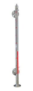
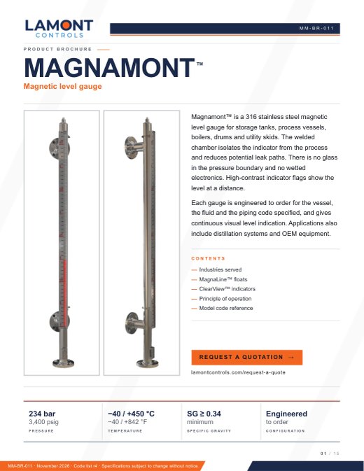
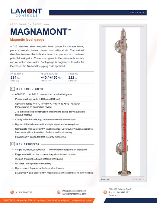
A 316 stainless steel magnetic level gauge for storage tanks, process vessels, boilers, drums and utility skids. The welded chamber isolates the indicator from the process and reduces potential leak paths. There is no glass in the pressure boundary and no wetted electronics. Each gauge is engineered to order for the vessel, the fluid and the piping code specified. High-contrast indicator flags show the level at a distance.
Pressure
3,400 psigfull vacuum to 234 bar
Temperature
−40…+842 °F−40…+450 °C
C-C length, standard to
18.5 ft222 in (5,640 mm)
Minimum SG
0.34float weighted for the fluid
Made in Canada
Construction
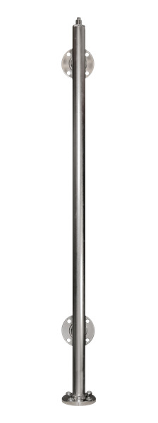
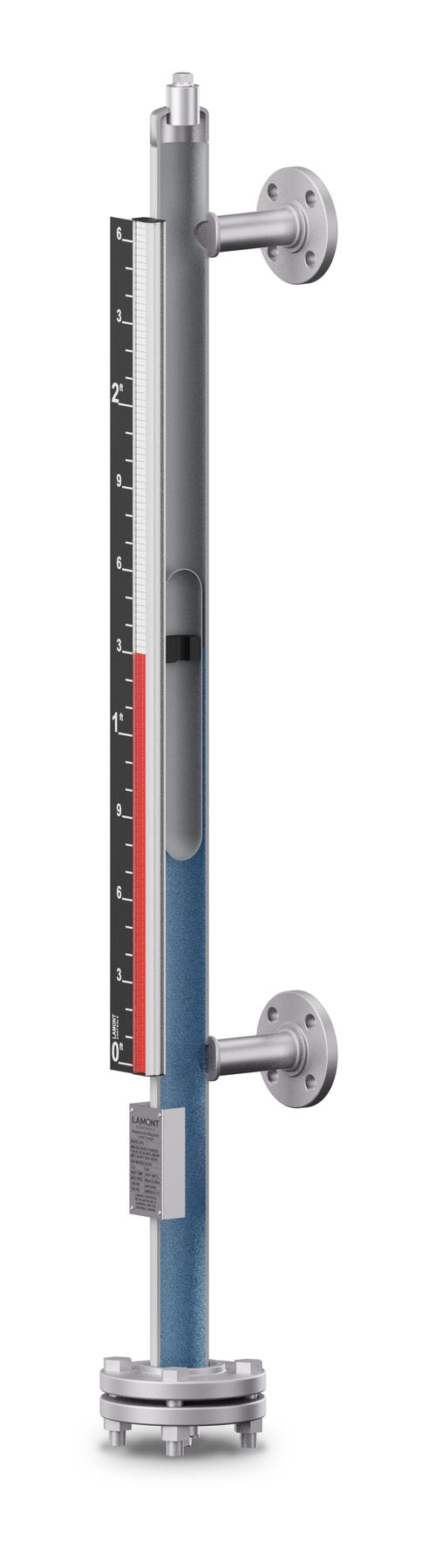
Front and side view
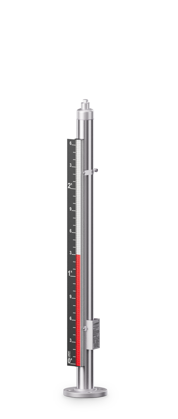
The welded 316 stainless steel chamber contains the float. The indicator and scale mount outside the chamber and have no contact with the process.
Shown
Side–side configuration
C-C
48 in (1,219 mm)
Connections
Flanged
Indicator
ClearView™ flags, scale in feet and inches
Float
MagnaLine™ titanium
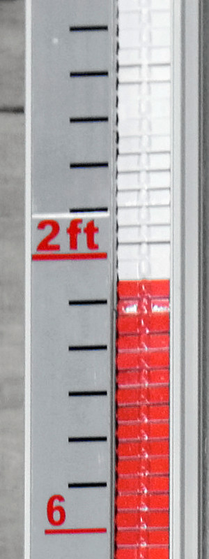
1Vent plug in the welded end cap2Flanged process connection on a welded nozzle3Black etched scale; flags turn red below the level4Indicator flags beside the Lamont mark at 0 ft
1VentThreaded ⅛ to 1 in; flanged ½ to 1 in
2Process connectionsFlanged, threaded or welded; ½ to 4 in
3ScaleEtched aluminum; imperial, metric, percent or volume
4IndicatorClearView™ flags, magnetically coupled to the float
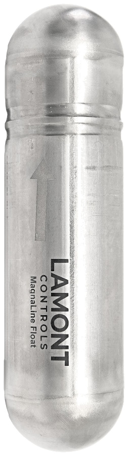
5MagnaLine™ floatTitanium, weighted for the fluid; floats at the liquid level
6ChamberWelded SS316; other alloys on request
7Bottom flangeBolted; drain connection per model code
FIG. 02 · Magnamont, side–side, 48 in centre-to-centre: front view left, side view right. The float is shown at the liquid level, where the flags change from white to red.
Configurations
Process connection configurations
Renders · dimensions per application5 configurations · renders
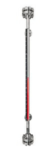
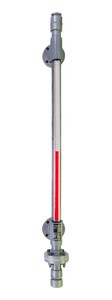
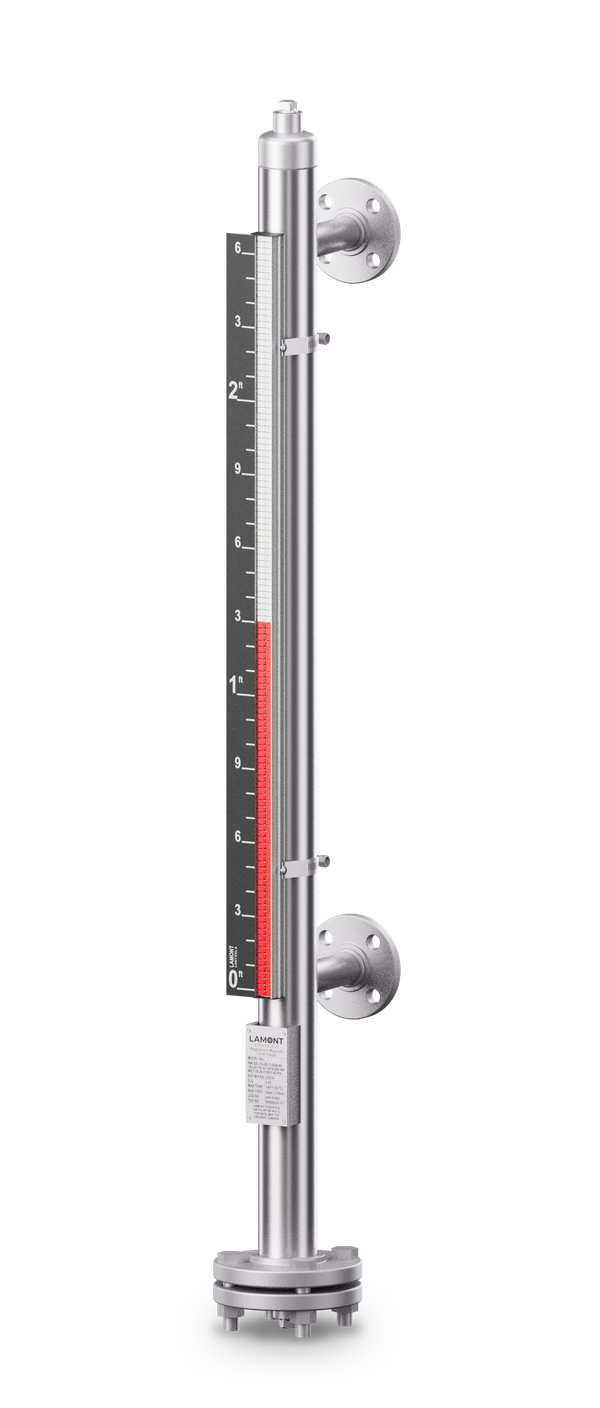
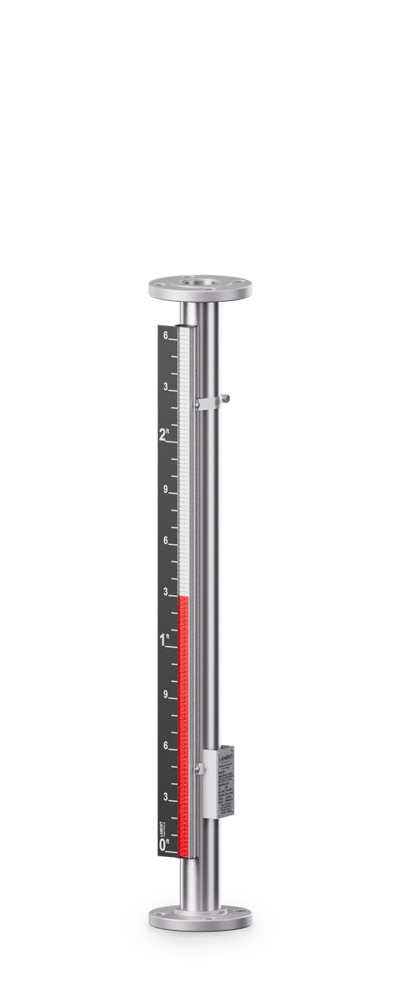
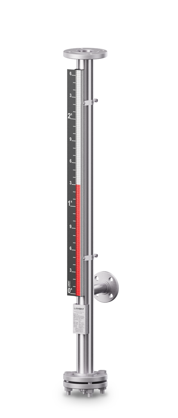
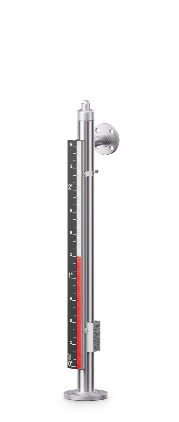
Side–sideStandard. Process connections on the side of the chamber, top and bottom.Top–bottomFlanged process connections on the top and bottom ends of the chamber.Top–sideOne process connection on the top end, one on the side at the bottom.Bottom–sideOne process connection on the bottom end, one on the side at the top.Top-mountChamber and indicator on a single flanged connection on the vessel top.
Product
Design features
Piping code construction. Heavy-duty schedule pipe; ASME B31.1 or B31.3 construction, or industrial grade.
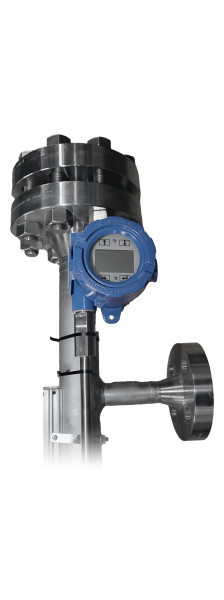
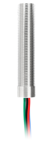
Automation without new nozzles. LevelSync™ and SurePoint™ clamp to the outside of the chamber.
Visible at a distance. High-contrast flags are isolated from the process and do not cloud or stain.
No glass in the pressure boundary. A welded, all-metal bypass chamber replaces the glass assembly.
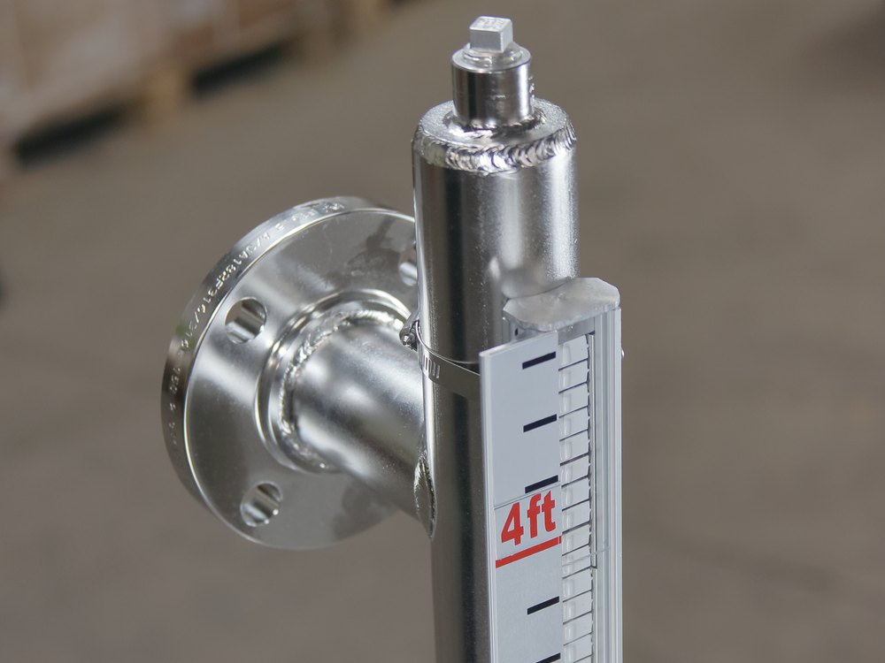
Vent plug, end-cap weld and flanged process connection.
Production photographs
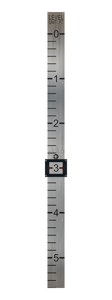
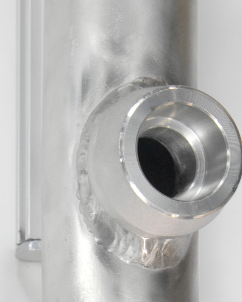
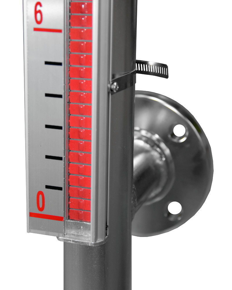
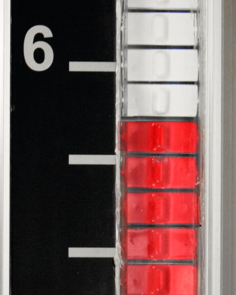
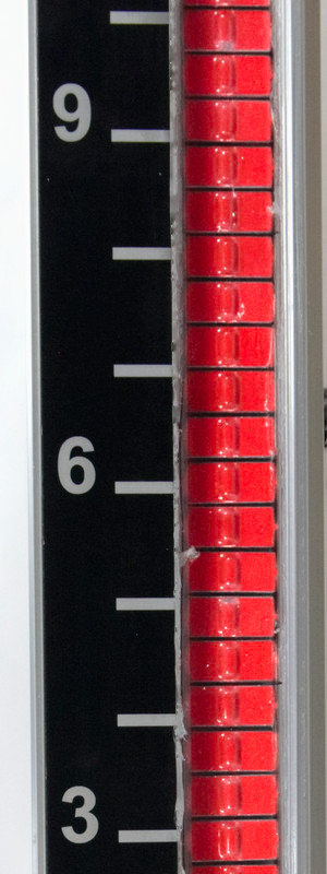
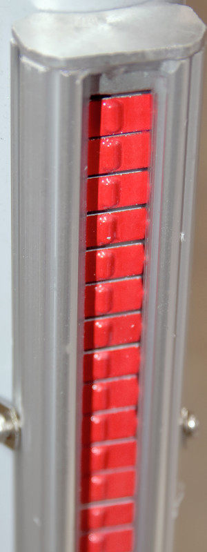
Socket-weld branch outletOutlet welded to the chamberScale and flagsEtched scale and indicator, banded to the chamberBlack etched scaleISFS-300 standard indicator: red flags beside the black etched aluminum scale
Operation
Principle of operation
Cutaway · animation to scale · section B–B · flag rotation
Cutaway · render, 30 in (762 mm) C-CAnimation · the cutaway beside it follows its level by percent of range
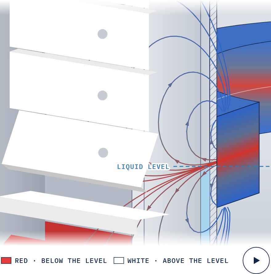
Section B–BPlan through the float magnet
Flag rotationFlags turning as the float's magnet ring passes: red below the level, white above.
Float. A sealed MagnaLine™ float carries a permanent magnetic assembly. The float is weighted for the fluid's specific gravity and floats at the liquid surface. As the level rises or falls, the float moves with it inside the chamber.
Magnetic coupling. The float's magnetic field couples through the chamber wall to the ClearView™ indicator mounted outside the chamber. The indicator follows the float and shows the level without contact with the process.
Visual indication. The indicator is a column of rotating flags in contrasting colours. Each flag turns as the float passes: one colour shows liquid below, the other vapour above. The reading is continuous.
Also available: HS-300. Hermetically sealed, argon-filled indicator in a stainless housing with scale · 572 °F (300 °C).
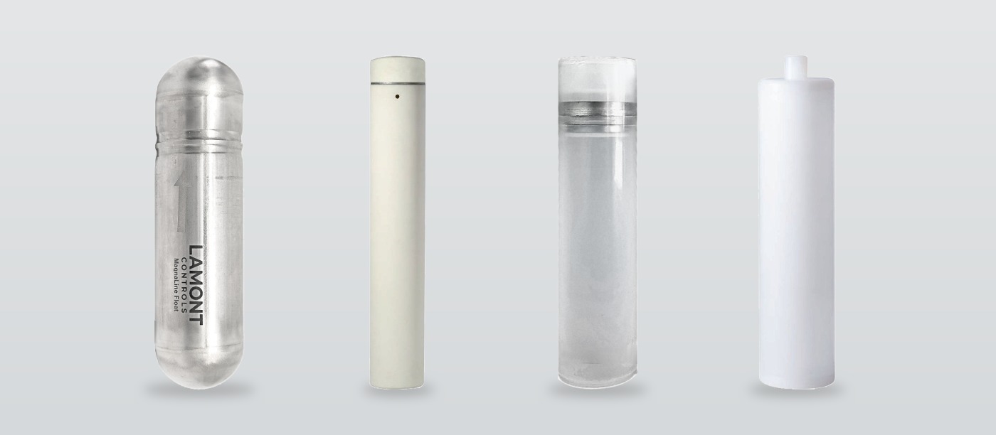
MagnaLine™ floats
TitaniumStandard
Titanium, precision-weighted for the fluid's specific gravity and operating pressure.
316 stainless steelOptional
316/316L stainless steel for heavier fluids and general industrial service.
Engineered and customConsult factory
High-pressure ball-segment, syntactic foam for extreme-pressure service, exotic alloys, coated and lined floats.
Minimum SG 0.34; the float's SG must be lower than the fluid's. Consult factory below SG 0.45 or for two-phase or solids-bearing service.
Automation
LevelSync™ transmitters and SurePoint™ switches
LevelSync™ · SurePoint™
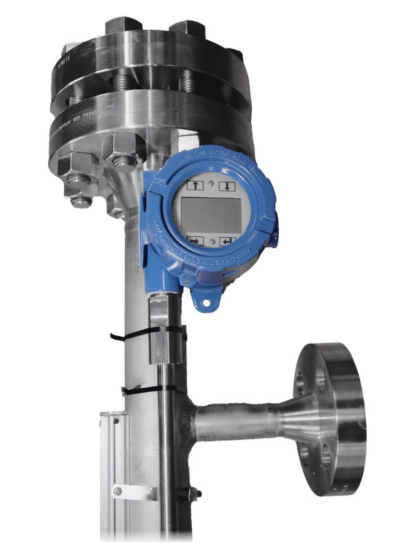
LevelSync™ transmitters and SurePoint™ switches are externally mounted and magnetically coupled to the gauge’s MagnaLine™ float. They have no wetted parts, require no additional vessel nozzle, and are fitted at the factory or in the field.
LevelSync™
Magnetostrictive level transmitter
Continuous level output from the gauge float by magnetostrictive time-of-flight sensing. No moving parts and no routine recalibration.
Output
4–20 mA with HART®; Modbus RTU or DDA optional
Accuracy
±0.039 in (±1 mm) inherent
Length
12 to 144 in (305 to 3,658 mm); longer on request
Process temp.
To 302 °F (150 °C); to 527 °F (275 °C) with thermal standoff
Hazardous area
Intrinsically safe or explosionproof; FM, FMc, ATEX, IECEx, UKCA
Housing
Epoxy-coated aluminum or 316L stainless; NEMA 4X, IP65
Order with option MLT in the gauge model code.
SurePoint™
Magnetic point-level switch
Leverless switch actuated by the float's magnet for high and low level alarms and basic control. No moving levers and no actuation power.
Contact
SPDT, latching
Rating
Up to 25 W resistive; 1 A at 24 VDC; 150 VDC · 230 VAC max
Hazardous area
Class I, Div. 1 (UL 1203); Class II, Groups E, F, G; gas groups confirmed at quotation
Switch temp.
−58 to +221 °F (−50 to +105 °C)
Housing
300-series stainless steel, factory sealed
Mounting
Band clamp; set point adjustable along the chamber
Hazardous-area certifications are held by Lamont's component manufacturing partner and apply to the supplied product. Final certification, temperature class and marking depend on configuration and are confirmed at quotation.
Data
Technical specifications
Ratings
Pressure
Full vacuum to 3,400 psig (234 bar)
Temperature
−40 to +842 °F (−40 to +450 °C); lower temperatures on application review
Measuring range
Standard lengths to 18.5 ft (222 in, 5,640 mm) centre-to-centre; longer lengths on request
Passivated per ASTM A380 / A967 (standard) · electropolished, external surfaces, per ASTM B912 · painted · powder coated
Connections
Process connections
Flanged; threaded (FNPT / MNPT); welded (Weldolet, Sockolet). ½ to 4 in NPS; DN15 to DN65; 15A to 50A
Flange classes
ANSI 150 to 1500 · DIN PN10 / 16 / 25 / 40 · JIS 5K to 20K (DIN and JIS special order) · other classes on request
Vent and drain
Threaded ⅛ to 1 in; flanged ½ to 1 in; custom ports; or none
Indication
Scales
Feet and inches · metres / cm · percent · gallons or litres to tank volume · custom · none
Scale material
Etched aluminum, resistant to UV, abrasion and chemical attack; marking to MIL-STD-130N. Non-metallic scales optional
Codes, testing and documentation
Construction code
Industrial grade (IG), ASME B31.1 (B1) or B31.3 (B3), specified in the model code
Pressure test
Pressure tested before shipment; hydrostatic test at not less than 1.5 × design pressure where specified; test reports available
Material traceability
Maintained throughout manufacturing; MTRs available
NDE
Per the governing code where required: visual examination, dye-penetrant examination of fillet welds, and positive material identification (PMI) where specified
Further inspection
Available on request
Options
FloatSense™ float-integrity monitoring (FS)
A clear visual signal at the indicator if the float loses buoyancy and sinks, so a failed float is not read as a low level.
Insulation blanket (IB)
Wraps the chamber; a clear window keeps the indicator readable.
Heat tracing (HT)
Freeze protection for cold-climate service.
Interface service (INT)
Float set for the second liquid's SG, specified in the model code.
Custom options (X)
Special accessories engineered to the application, on request.
Ratings. Pressure and temperature ratings depend on materials, connections and configuration, and are confirmed at quotation.
Custom configurations. Non-standard lengths, exotic alloys and special process connections on request. Contact Lamont Controls Engineering.
Quality
Quality, testing and documentation
Build and test sequence · documents
01
Approval drawing
Issued after the purchase order. The design is confirmed on the drawing before fabrication starts.
02
Material
Material traceability is maintained throughout manufacturing.
03
Construction code
Built to ASME B31.1 or B31.3, or industrial grade, as specified in the model code.
04
NDE
Per the governing code where required: visual examination, dye-penetrant examination of fillet welds, and positive material identification (PMI) where specified.
05
Pressure test
Pressure tested before shipment; hydrostatic test at not less than 1.5 × design pressure where specified.
06
Float and indicator
The float is weighted for the fluid’s specific gravity. The indicator and scale mount outside the chamber.
Documents
Material test reports (MTRs)
Available
Hydrostatic test reports
Available
Approval drawing
Issued after the purchase order
Certificate of origin
Chamber-of-commerce certified, on request
Further inspection
Available on request
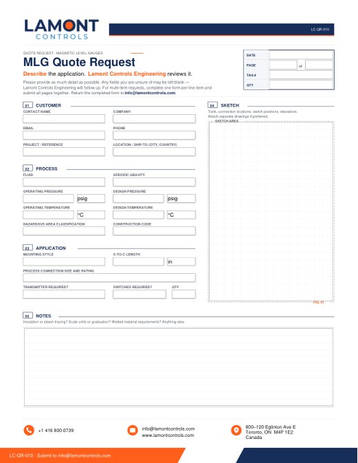
Quotation
Request a quotation
Complete the process conditions below, or attach a datasheet or drawing. Fields marked * are required. Process data speeds up the quotation.
For a general enquiry, select Quick message and provide your contact details with a brief note.
For a replacement, attach a photo of the existing nameplate and enter the centre-to-centre dimension.
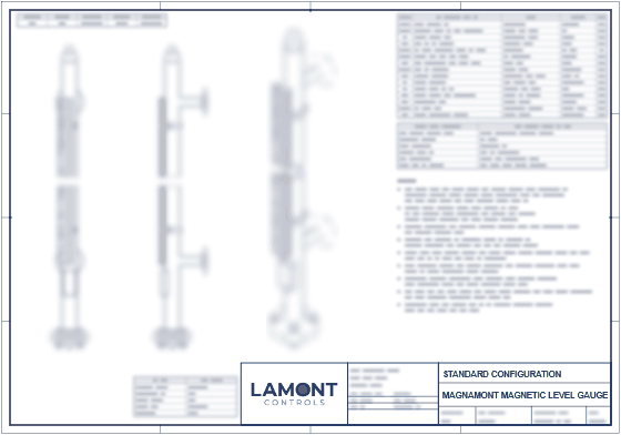
LAMONT CONTROLS ENGINEERING · SENT AFTER REVIEWDimensional drawingsOutline drawings for the standard Magnamont™ configurations, one sheet each: side–side, top–bottom, top–side, bottom–side and top-mount. Sent by Lamont Controls Engineering after review; final dimensions are on the approval drawing, issued after the purchase order.
Cooling-tower sumps, boiler rooms and generator day tanks, often with SurePoint™ switches.
OEM and equipment builders
Compressor packages, pump skids and boilers. One approved drawing covers repeat production runs.
Also serving food and beverage · airports and deicing · mining and metals · steel production · research facilities. For aggressive corrosives, see Polysight™; for extreme pressure and temperature, see Fortimag™.