
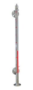
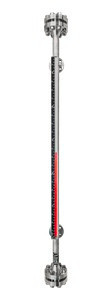
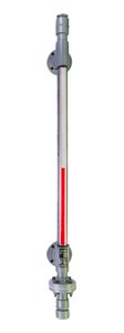
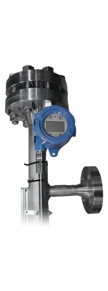
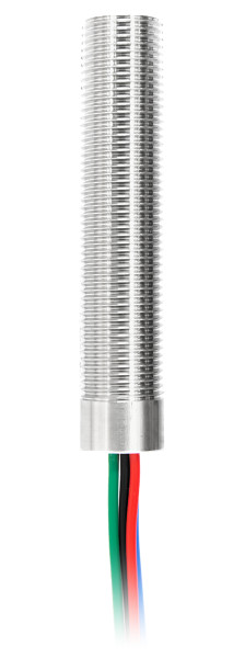
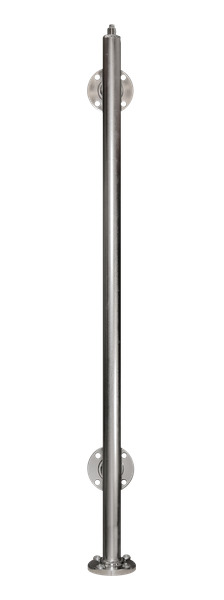
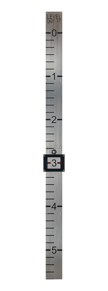
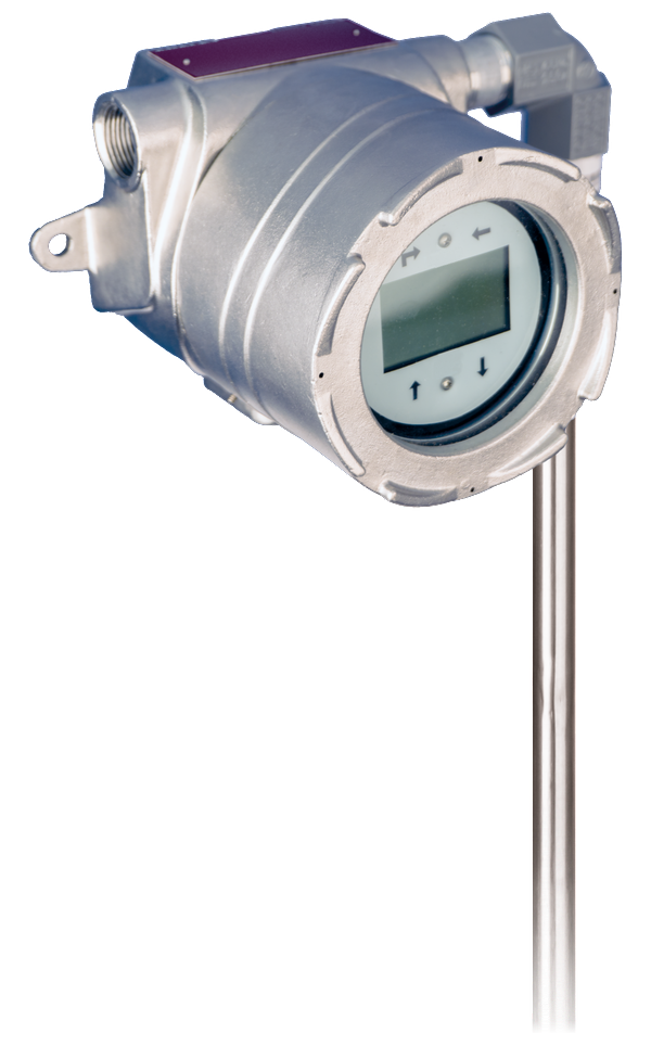
with integral local display
LevelSync™ Magnetostrictive level transmitter
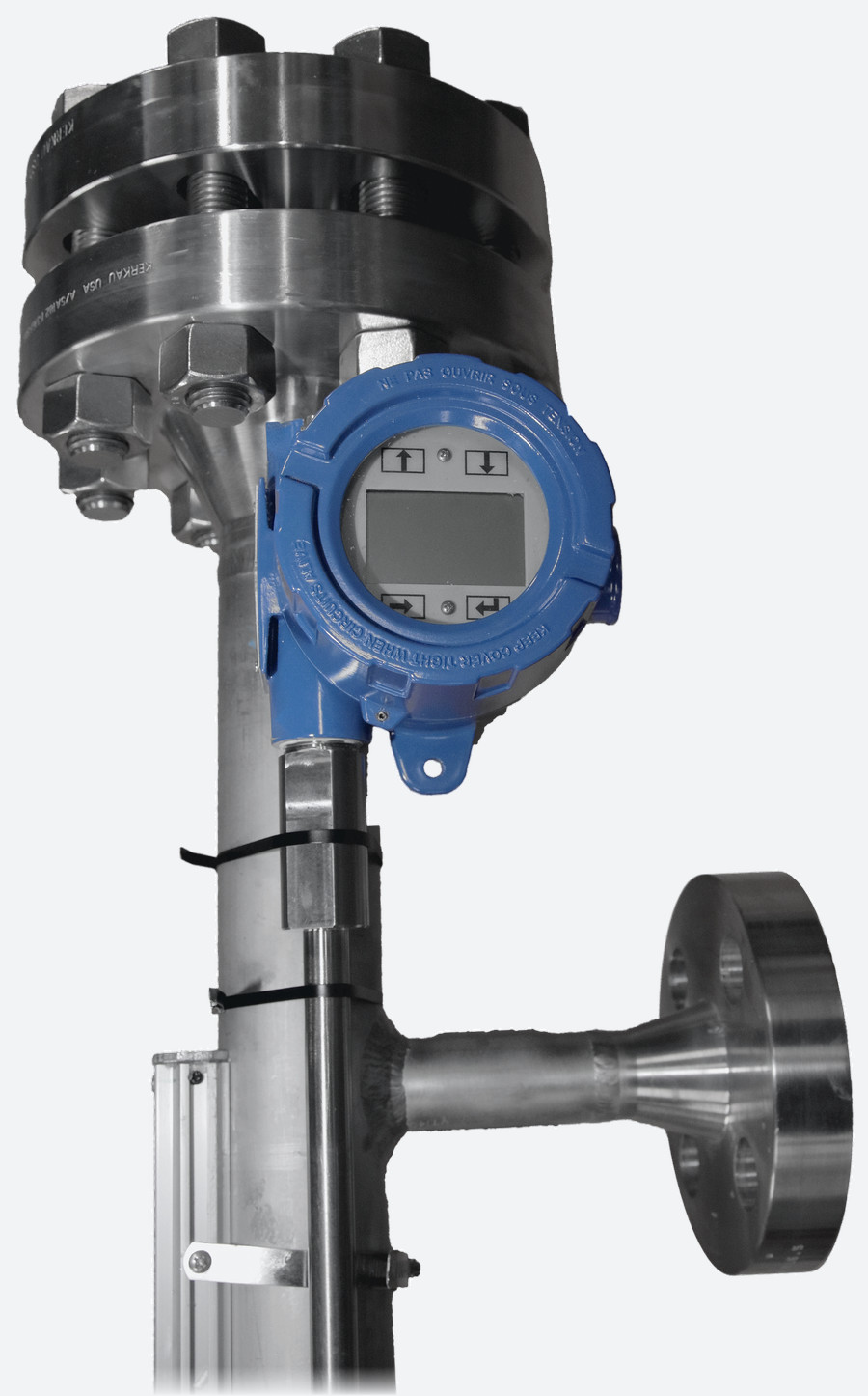
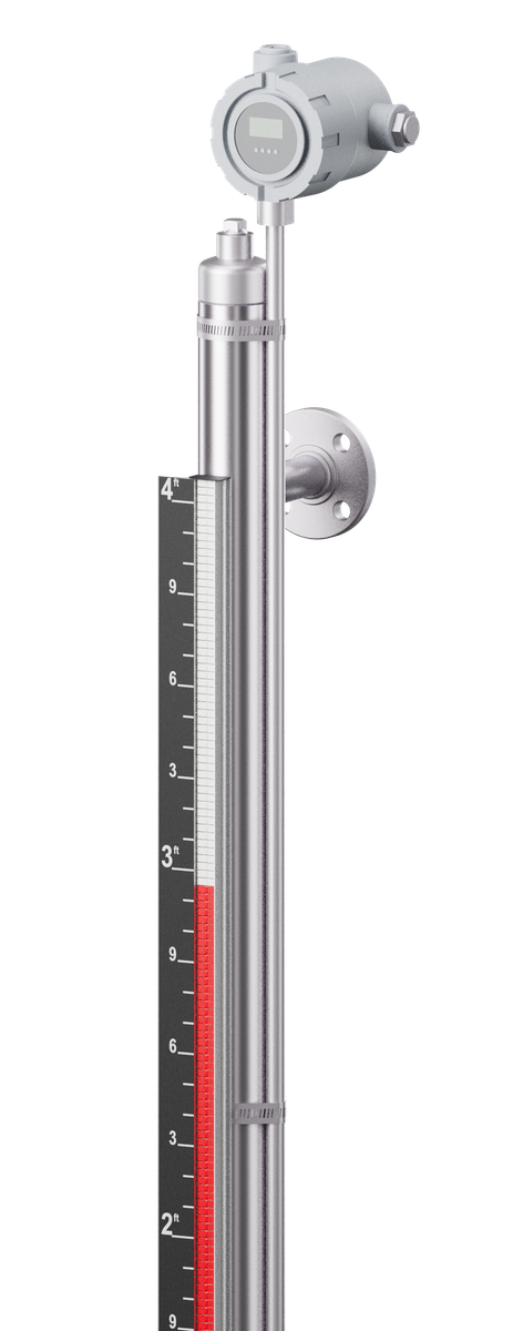
LevelSync is the Lamont Controls magnetostrictive level transmitter, supplied and configured for Lamont magnetic level gauges. It mounts outside the gauge chamber and reads the same float that drives the indicator. The electronics are isolated from the process, with no wetted parts and no additional vessel nozzle. Time-of-flight sensing provides a continuous, high-accuracy 4–20 mA signal with HART®. The transmitter has no moving parts and needs no routine recalibration. It is fitted at the factory under option MLT, or added to a gauge in the field.
- Output
- 4–20 mAwith HART®; Modbus RTU or DDA optional
- Inherent accuracy
- ±0.039 in±1 mm
- Hazardous area
- IS / XPintrinsically safe or explosionproof
- Wetted parts
- Nonemounts outside the chamber
Operation
Principle of operation
- Float. The magnetic float inside the gauge chamber follows the liquid surface. The same float turns the indicator flags, so no second float or vessel connection is required.
- Magnetic coupling. The LevelSync sensor rod is mounted outside the chamber. The float's magnetic field couples to the rod through the chamber wall. Sensing is external and non-wetted, with no moving parts.
- Time-of-flight measurement. The transmitter locates the float magnet along the sensor rod by magnetostrictive time-of-flight measurement and sends a continuous 4–20 mA signal with HART® to the control system. The measurement range equals the indication length of the gauge.
Transmitters and switches on the gauge: full principle of operation
Integration
Fitted to Lamont gauges
- Outside the chamber. The transmitter clamps to the gauge chamber, with no wetted parts and no additional vessel nozzle or penetration.
- Same float as the indicator. Operators read the level at the vessel. The control system receives a continuous signal from the same float.
- Factory or field. Fitted at the factory under option MLT, or added in the field. Installation and calibration can be performed while the vessel remains in operation.
- Long gauges and hot service. Above 75 in (1,905 mm) centre-to-centre or 302 °F (150 °C), the transmitter is bottom mounted with a 90° bend. From 302 to 527 °F (150 to 275 °C), a thermal standoff is added. Above 527 °F (275 °C), consult factory.
- Transmitter-only service. The gauge can be ordered without an indicator (code IX) where only the transmitter signal is required.
Compatible with
- Magnamont™SS316 magnetic level gauge, to 3,400 psig→
- Fortimag™Extreme pressure and temperature service, to 5,000 psig→
- Polysight™Thermoplastic, for corrosive service, to 150 psig→
Option MLT is position 18 of each gauge's model code. For a gauge already in service, see Request a quotation.
Applications: Produced water · Deaerators and boiler feed tanks
Data
Technical specifications
Measurement
| Measured variable | Liquid level (total or interface, application dependent) |
|---|---|
| Measuring principle | Magnetostrictive, time-of-flight |
| Sensing method | External, non-wetted, magnetic coupling to the gauge float |
| Measurement range | Equal to the magnetic level gauge indication length |
| Order length | 12 to 144 in (305 to 3,658 mm); longer lengths on request |
| Inherent accuracy | ±0.039 in (±1 mm) |
| Repeatability | ±0.015 in (±0.381 mm) or ±0.001 % F.S., whichever is greater |
Output and electrical
| Output signal / protocol | 4–20 mA with HART® · Modbus RTU or DDA (optional) · SIL 2 version (4–20 mA / HART®) available on request |
|---|---|
| Supply voltage | 10.5 to 28 VDC (loop powered) |
| Fail-safe mode | Analog / HART®: low (3.5 mA, default) or high (22.8 mA) Modbus / DDA: high, full scale |
| Reverse polarity protection | Yes |
| Wiring | 4-wire shielded cable or twisted pair · 6-pin male connector · 180 in (4,572 mm) integral cable with pigtail |
| Electrical connection | ¾ in FNPT conduit opening (M20 for ATEX / IECEx / UKCA versions) · ½ in FNPT (NEMA Type 4X) |
| EMC compliance | EN 61326-1, EN 61326-2-3, EN 61326-3-2, EN 61000-6-2/-3, EN 61000-4-2/-3/-4/-5/-6/-8 |
Temperature and environment
| Ambient (electronics) | −40 to +160 °F (−40 to +71 °C) |
|---|---|
| Sensing element | −40 to +257 °F (−40 to +125 °C) |
| Process temperature (gauge) | Up to 302 °F (150 °C): standard mounting 302 to 527 °F (150 to 275 °C): thermal standoff, bottom mounted with a 90° bend Above 527 °F (275 °C): consult factory |
| Humidity | 0 to 100 % relative humidity, no condensation |
| Enclosure rating | NEMA Type 4X, IP65 |
Mounting and materials
| Mounting | External mounting to the magnetic level gauge chamber |
|---|---|
| Mounting orientation | Top, bottom or side (application dependent). Bottom mounted with a 90° bend above 75 in (1,905 mm) centre-to-centre or above 302 °F (150 °C) |
| Wetted parts | None |
| Housing | Epoxy-coated aluminum (standard) or 316L stainless steel (option) |
| Sensor rod | 316L stainless steel |
Hazardous area
| Intrinsically safe (IS) | Class I, Div. 1 / Zone 0–1, Gas Groups A–D / IIC |
|---|---|
| Explosionproof / flameproof | Class I, Div. 1 / Zone 1, Gas Groups B–D / IIB + H₂ |
| Regional approvals | NEC / CEC (FM, FMc), ATEX, IECEx, UKCA |
- Certification. Hazardous-area certifications are held by Lamont's component manufacturing partner and apply to the supplied product. Final certification, temperature class and marking depend on configuration and are confirmed at quotation.
Ordering
Ordering information
| Code | Description | Model code |
|---|---|---|
| MLT | LevelSync™ magnetostrictive level transmitter | Position 18, Options (stackable), in the Magnamont™, Fortimag™ and Polysight™ model codes |
Output protocol, housing and hazardous-area rating are specified with the order. An integral local display is available. For options not listed on LS-TS-010, consult factory.
Sample code, FM-MC-010 · Class 900 · B31.1 · custom-machined ports · transmitterFM-SS-316-02-TI-SG0.88-900-B1-FL-01-ISFS-300-NF-IMP-66.0V-CS-05-CS-05-PA-MLT
Quotation
Request a quotation
Select With a new Lamont gauge to have the gauge and transmitter quoted together, or For an existing gauge to have the transmitter quoted alone. Fields marked * are required. Process data speeds up the quotation.
For an existing gauge, attach a photo of the installed gauge and its nameplate.
For a general enquiry, select Quick message and enter contact details with a brief note.
What happens nextLamont Controls Engineering reviews the conditions and replies within 1 to 3 business days with a quotation.
1-833-7LAMONT info@lamontcontrols.comDownloads
Documentation
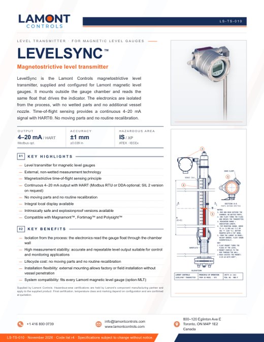 LS-TS-010 · NOVEMBER 2026Technical specification sheetDownload
In this sheet
- Page 1. Overview, key figures and benefits.
- Page 2. Technical specifications: measurement, output, temperatures, mounting, materials, hazardous-area approvals and ordering.
Gauge model codes. Option MLT is listed in the model code references on the Magnamont, Fortimag and Polysight pages.