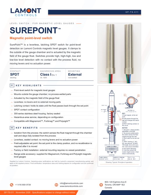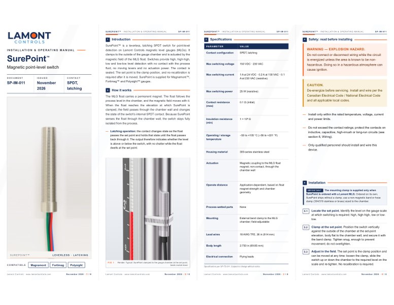
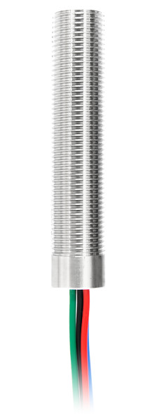
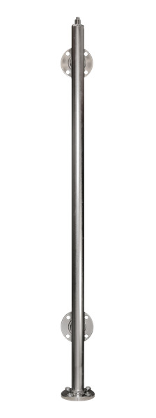
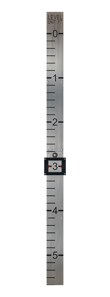

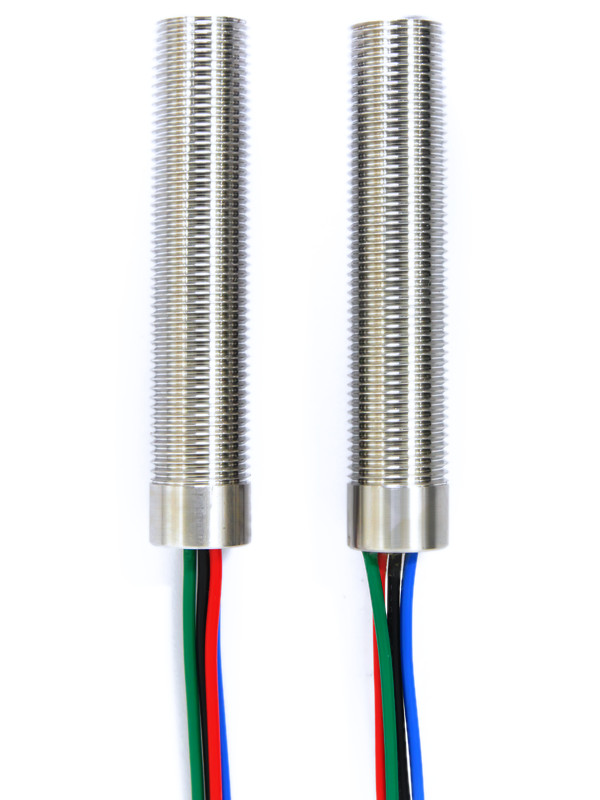
18 AWG flying leads
SurePoint™ Magnetic point-level switch
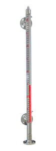
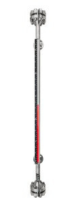
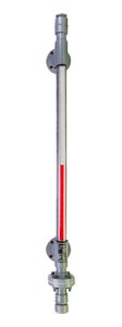
SurePoint is a leverless, latching SPDT magnetic level gauge switch for Lamont gauges. It clamps to the outside of the gauge chamber and is actuated by the magnetic field of the gauge float. Switches provide high, high-high, low and low-low level detection with no contact with the process fluid, no moving levers and no actuation power. The set point is the clamp position and can be moved along the chamber at any time without recalibration. Each gauge takes 1 to 8 switches, ordered with a new Magnamont™, Fortimag™ or Polysight™ gauge or added to an installed Lamont gauge.
- Contact
- SPDT, latchingup to 25 W resistive, 150 VDC · 230 VAC max
- Hazardous area
- Class I, Div. 1explosionproof, per UL 1203
- Operating temperature, switch
- −58…+221 °F−50…+105 °C, outside the chamber
- Process-wetted parts
- Noneclamps to the outside of the chamber
Supplied by Lamont Controls
Operation
Principle of operation
- Float magnet. The gauge float carries a permanent magnet. The float follows the process level in the chamber, and the magnetic field moves with it.
- Magnetic actuation. When the float reaches the elevation of the switch, the field passes through the chamber wall and changes the state of the switch's internal contact. The switch is leverless: it has no moving levers and requires no actuation power.
- SPDT output, isolated from the process. SurePoint senses the float through the chamber wall, so the switch stays fully isolated from the process. The SPDT contact switches high and low level alarms or basic control circuits. The contact is latching: it holds its state until the float passes back.
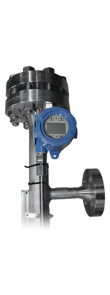
Transmitters and switches on the gauge: full principle of operation
Installation
Mounting and set points
SurePoint is a clamp-on level switch, held to the outside of the gauge chamber by an adjustable band clamp. External mounting requires no vessel penetration, so switches can be fitted at the factory or in the field.
- Locate the set point. Identify the level on the gauge scale at which switching is required: high, high-high, low or low-low.
- Clamp to the chamber. Position the switch vertically against the outside of the chamber at the set-point elevation, body flat to the chamber wall, and secure it with the band clamp. Tighten snug; do not overtighten.
- Adjust in the field. The set point is the clamp position: loosen the clamp, slide the switch to the scale reading and re-tighten. No recalibration is required.
- Use non-magnetic hardware. The clamp and nearby brackets and fasteners must be 300-series stainless (304/316) or brass. 400-series stainless and plated steel are magnetic and can shift the trip point.
- Route the leads. Support the leads so the switch does not carry their weight, and route them down to the junction box, controller or relay panel, away from high-energy power runs.
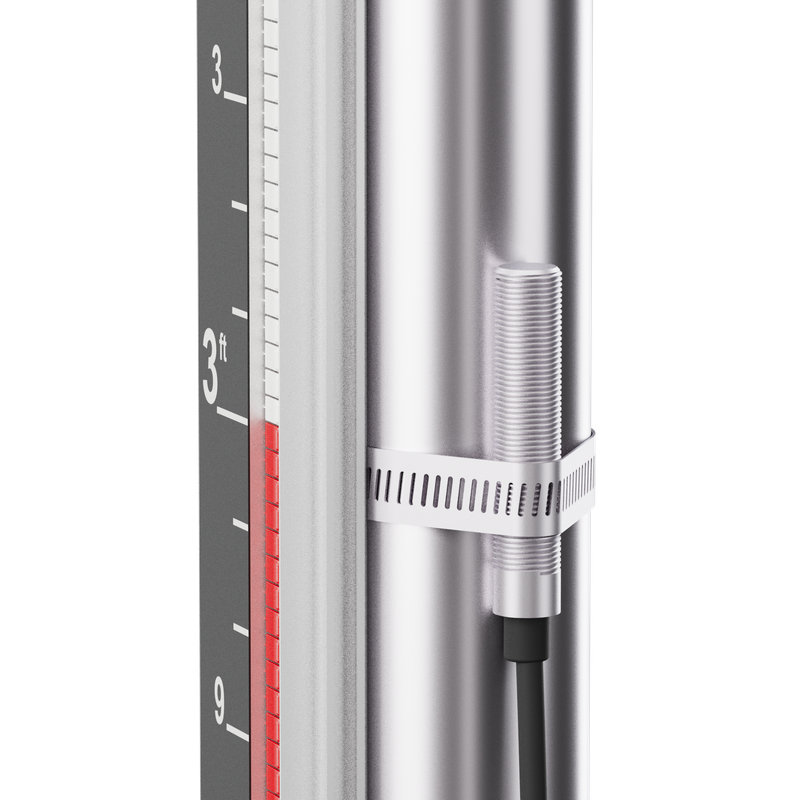
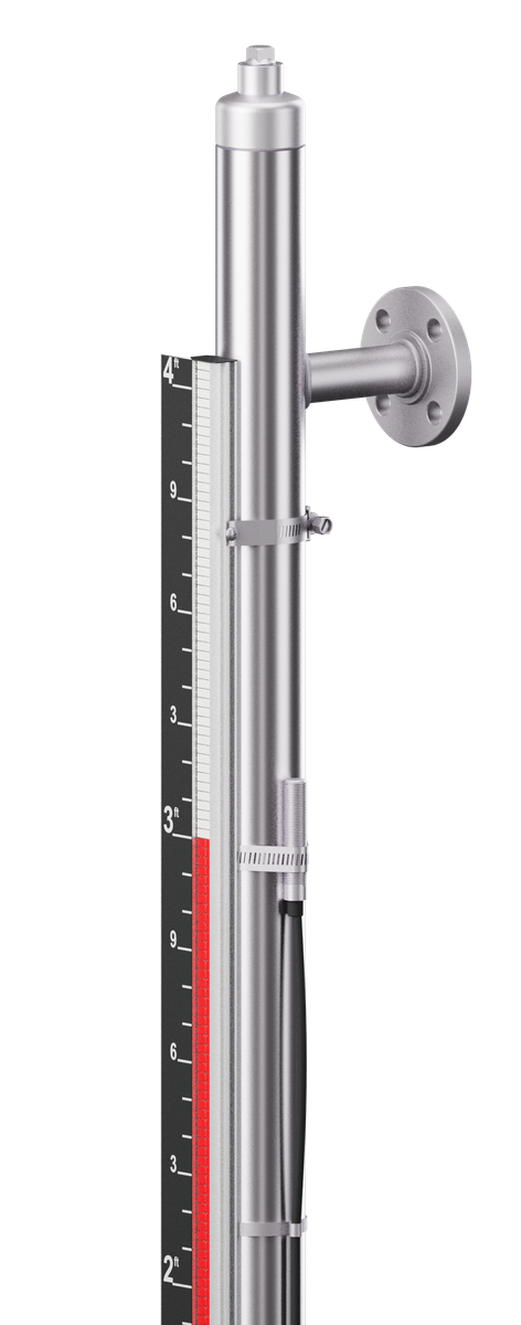
1 to 8 switches per gauge (options PLS-1 to PLS-8), each clamped at its own set point.
Applications: Deaerators and boiler feed tanks · Marine tanks · LPG and propane
Data
Technical specifications
Switching
| Contact configuration | SPDT, latching |
|---|---|
| Switching voltage (max) | 150 VDC · 230 VAC |
| Switching current (max) | 1 A at 24 VDC · 0.2 A at 130 VAC · 0.1 A at 230 VAC (resistive) |
| Power rating | Up to 25 W (resistive). Use an interposing relay or contact protection for inductive or high-inrush loads. |
| Contact resistance (max) | 0.1 Ω (initial) |
| Insulation resistance (min) | 1 × 10⁹ Ω |
| Electrical connection | Flying leads |
| Lead wires | 18 AWG TFE, 36 in (914 mm) standard; custom lengths on request |
Typical wiring
| Contacts | Common (C), normally open (NO), normally closed (NC), plus ground |
|---|---|
| Lead colours | Identified on the switch delivered |
| Contact protection | For inductive, capacitive or high-inrush loads, use an interposing relay or a contact-protection network (RC snubber, MOV or flyback diode as appropriate). On long runs, drive an interposing relay near the switch rather than the final load. |
| Series / parallel | Several switches may be wired in series or parallel to suit the control logic; observe the contact ratings for the combined load. |
Operation
| Operating principle | Magnetic actuation by the gauge float magnet · leverless, no-touch sensing · external mounting, non-wetted design |
|---|---|
| Actuation | Magnetic coupling to the float magnet, through the chamber wall |
| Operate distance | Application-dependent, based on float magnet strength and chamber geometry |
| Process-wetted parts | None |
Construction and mounting
| Housing material | 300-series stainless steel |
|---|---|
| Construction | Factory sealed |
| Mounting | External clamp-on mounting to the gauge chamber |
| Mounting method | Adjustable band clamp / hose clamp (standard) |
| Set point | Set by the clamp position; field-adjustable |
| Compatible with | Magnamont™ · Fortimag™ · Polysight™ |
Temperature, at the switch body
| Operating temperature | −58 to +221 °F (−50 to +105 °C) |
|---|---|
| Storage temperature | −58 to +221 °F (−50 to +105 °C) |
Hazardous area and compliance
| Hazardous location | Class I, Division 1 (UL 1203) · Class II, Groups E, F, G (CSA C22.2 No. 25). Gas groups confirmed at quotation |
|---|---|
| Temperature code | Confirmed at quotation |
| Protection method | Explosionproof / dust-ignition proof (per UL 1203) |
| Standards | UL 1203 · UL 508 / CSA C22.2 No. 14-13 · CSA C22.2 No. 25-1966 · CSA C22.2 No. 30-M1986 · ATEX 2014/34/EU · IECEx · Low Voltage Directive 2014/35/EU · RoHS2 Directive 2011/65/EU |
- Hazardous area. Hazardous-area certifications are held by Lamont's component manufacturing partner and apply to the supplied product. Final certification, temperature class and marking depend on configuration and are confirmed at quotation.
- Temperature. Operating and storage ratings apply at the switch body, which mounts outside the gauge chamber.
Model code
Ordering information
| PLS-1 to PLS-8 | SurePoint™ clamp-on switches, quantity 1 to 8. Selected at position 18 (options) of the Magnamont™, Fortimag™ and Polysight™ model codes; can be combined with the other options. |
|---|---|
| With a new Lamont gauge | Add the option to the gauge model code and state the alarm duty of each switch and, where known, its set point. The mounting clamp is supplied with the gauge. |
| For an installed Lamont gauge | State the gauge model code or serial number, or send a photo of its nameplate, with the set point of each switch where known. Ordered for an installed gauge, SurePoint ships without a clamp; use a non-magnetic band or hose clamp (304/316 stainless or brass) sized to the chamber. |
Quotation
Request a quotation
For switches on a new gauge, enter the process conditions and, where known, the set point of each switch. Fields marked * are required. Process data speeds up the quotation.
For an installed Lamont gauge, enter its model code or serial number and attach a photo of the nameplate.
For a general enquiry, select Quick message and provide your contact details with a brief note.
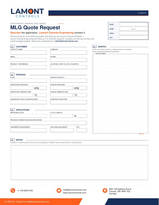
Alternatively, complete the fillable quote request form (PDF) and return it by email.
What happens nextLamont Controls Engineering reviews the request and replies within 1 to 3 business days with a quotation.
1-833-7LAMONT info@lamontcontrols.com