
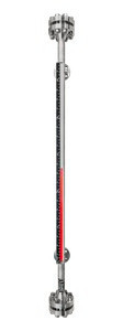
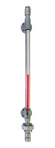

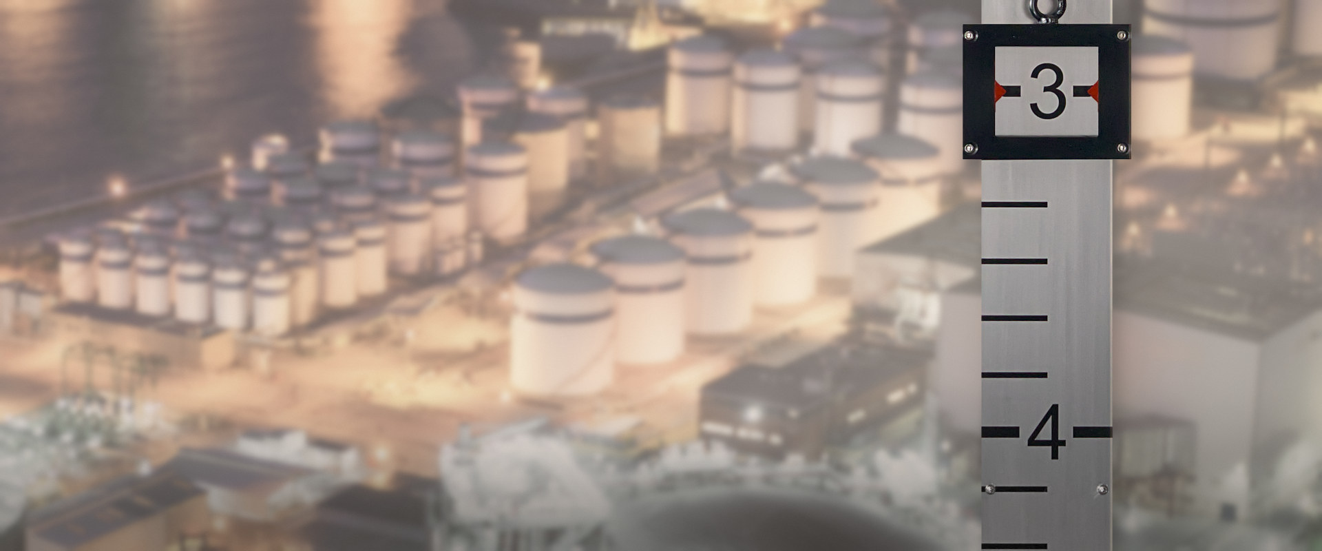
Target at 3 ft, red pointers
Plumbline™ Float-and-board tank level gauge
Plumbline™ is a float and board level gauge, also known as a target level indicator, for fixed-roof, vented atmospheric storage tanks. A stainless steel float in the tank is linked by a measuring wire to a target that travels on a scale board on the outside of the tank wall, where the level is read directly. The gauge requires no power and has no glass. Every penetration is on the tank roof; none is below the liquid level. Each gauge is built to the tank height, the specific gravity of the fluid and the scale units on the order.
- Service
- Atmosphericfixed-roof, vented tanks
- Fluid temperature, to
- 302 °F150 °C
- Measuring range, to
- 49 ft15 m · per order, set by the tank height
- Float and wires
- 304 SSfloat set for the specified SG
Ambient −4 to +176 °F (−20 to +80 °C) · suitable for outdoor installation
Operation
Principle of operation
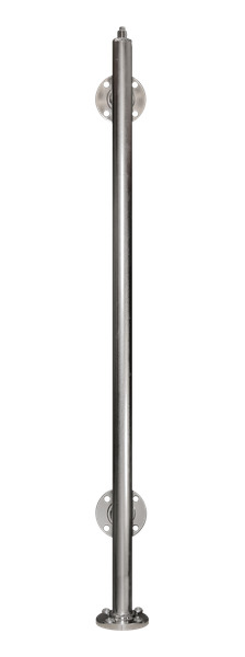
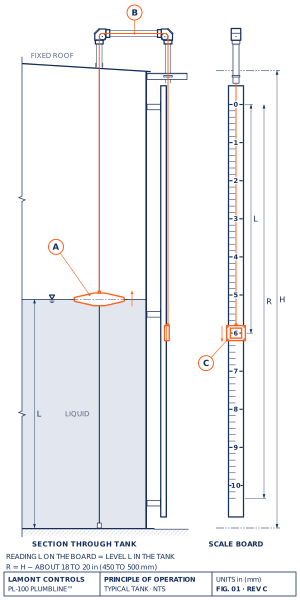
- Float. A 304 stainless steel float rides on the liquid surface. Two guide wires, tensioned between anchors on the roof and on the tank floor, hold it in position. The float and counterweight are set for the specific gravity stated on the order.
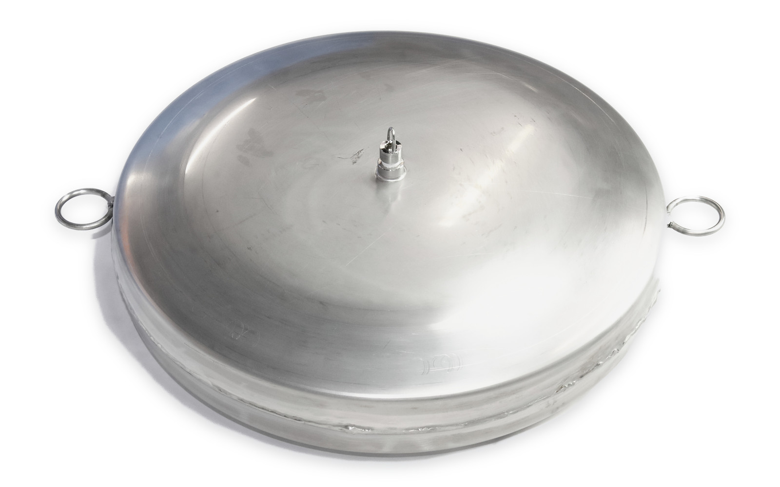
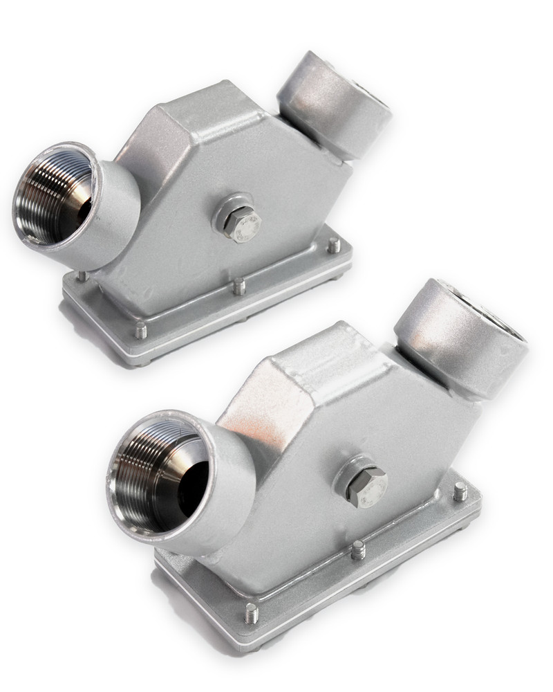
Float, with a guide-wire ring on each side - Measuring wire. A stainless steel measuring wire runs from the float up through the roof, over two sheave elbows, and down the outside of the tank to the counterweight.
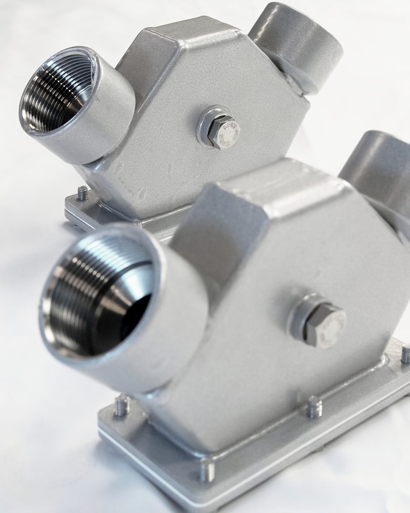
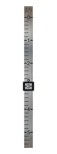
Sheave elbows - Target and scale board. The counterweight carries a target window with arrow pointers and travels on a vertical scale board on the tank wall. As the level rises, the float rises and the target descends. The target is at the top of the board when the tank is empty and at the bottom when it is full, so the scale is numbered from the top down.
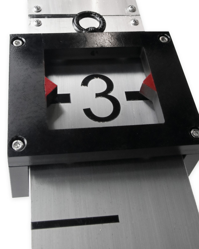
Target with arrow pointers
Fixed-roof tanks only. The guide wires and the measuring wire pass through the roof.
Construction
Construction and materials
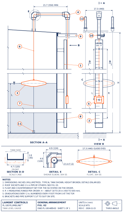
The float, measuring wire, guide wires and bottom anchor are 304 stainless steel. Outside the tank, the scale board is a cast aluminum channel with 304 stainless steel scale plates, mounted on stainless steel brackets cut to suit on site. The roof sockets, the roof pipe and the fixing of the bottom anchor are by others.
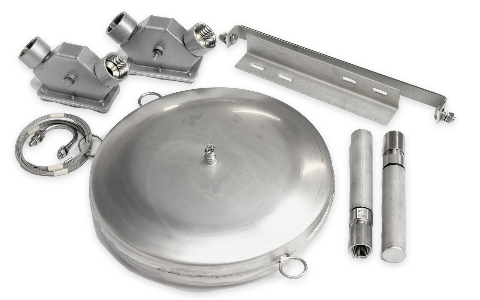
- 1Scale caseCast aluminum channel, 4.7 × 1.8 in (120 × 45 mm)
- 2Scale plates304 SS, 0.03 in (0.8 mm), 4.6 in (118 mm) wide, in sections of about 3 ft (914 mm); black marking
- 3Float304 SS, sized at the factory for the specified SG
- 4Sheave elbows (2)304 SS, 4.9 × 4.9 in (124 × 124 mm), for 1½ in pipe
- 5Counterweight with targetCarbon steel and cast aluminum, 5.9 × 4.7 in (150 × 120 mm), with arrow pointers
- 6Measuring wire304 SS, Ø 0.06 in (1.5 mm)
- 7Guide wires (2)304 SS, Ø 0.12 in (3 mm), 17.3 in (440 mm) apart, tensioned from the top anchors to the bottom anchor
- 8Brackets304 SS
- 9Pipe support304 SS
- 10U-bolts and nuts304 SS, for 1½ in pipe
- 11Bottom anchor304 SS channel, 17.3 × 1.6 in (440 × 40 mm), bolted to the tank floor
- 12Top anchors (2)316L SS with 304 SS; 1 in male, about 8.8 in (224 mm) long
Supplied by others
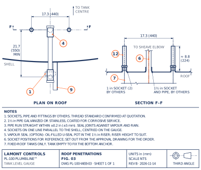
- Roof penetrations. Three sockets on the roof: two 1 in for the top anchors and one 1½ in for the measuring wire.
- Roof pipe and sockets. 1½ in pipe, galvanized or stainless, coated for corrosive service, with at least 21.7 in (550 mm) between the two sheave elbows.
- Bottom anchor fixing. The anchor is fixed to the tank floor. This requires an empty tank and tank entry, and may require hot work.
- Thread standard. For the sockets, pipe and fittings: confirmed at quotation.
Application
Typical services
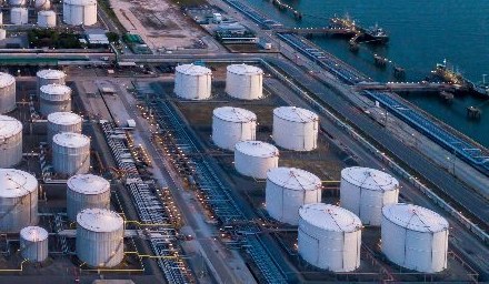
Suited to fixed-roof, vented atmospheric storage tanks with fluid temperatures to 302 °F (150 °C), in services such as:
- Water and wastewater
- Fire and process water
- Crude and refined oils
- Fuels
- Glycols
- Vegetable oils
- Other liquids compatible with 304 SS
Other services on application. Parts in the tank are 304 stainless steel. For toxic or odorous vapours, specify the vapour seal (VS).
Comparison
Float and board vs magnetic level gauge: local reading or remote signal
Three ways to read storage tank level, from a local reading only to a local reading with a signal to the control system.
 Plumbline™Float and board | 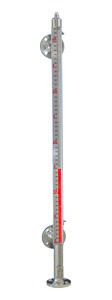 Magnetic level gauge | 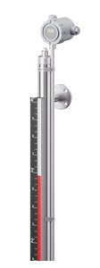 LevelSync™Magnetic level gauge with transmitter | |
|---|---|---|---|
| Reading | A target on a scale board on the tank wall, read from outside the tank | A column of coloured flags on a chamber beside the tank | The same column of coloured flags, and a continuous signal to the control system |
| Power | None | None for the local reading | None for the local reading; required for the transmitter |
| Level signal | None; Plumbline™ gives a local reading only | Local reading; switches optional | 4–20 mA with HART®; Modbus RTU or DDA optional |
| Tank connections | Roof only; none below the liquid level | Two, usually nozzles on the shell | Two, the same as the gauge; no additional nozzle for the transmitter |
| In the tank | Float on two guide wires; anchor on the tank floor | Nothing; the float rides in the external chamber | Nothing; the transmitter clamps to the outside of the chamber, with no wetted parts |
| Tank pressure | Atmospheric: fixed-roof, vented tanks | From atmospheric tanks to high-pressure vessels, by chamber design | As the gauge, by chamber design |
| Installation | Tank empty to fix the bottom anchor | Two shell nozzles at the gauge centre-to-centre | Factory-fitted, or added in the field to an existing gauge |
| Typical use | Local reading on tall storage tanks | Process vessels and tanks, local reading | Local reading with remote indication and control |
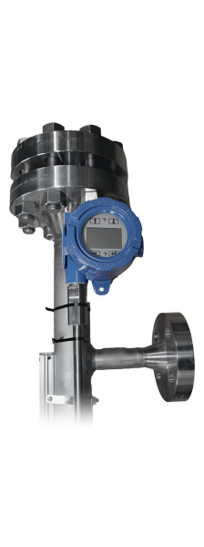
Magnetic level gauges from Lamont. Magnamont™ in 316 stainless steel and Polysight™ in CPVC or PVDF for corrosive service, each available with a LevelSync™ transmitter.
Float and board vs radar. Radar gives a signal but no local reading without power. Where radar is specified, a guided-wave radar can be fitted in a Lamont level bridle or external chamber beside a magnetic level gauge.
Selection
When a float-and-board gauge is the right choice
Suited to
- A fixed-roof, vented atmospheric tank. The roof may be cone, dome or flat; the guide wires and the measuring wire pass through it.
- A local reading for operators. The target is read on the tank wall, from outside the tank, with no power and no electronics.
- A tall tank. One scale board covers the measuring range, up to 49 ft (15 m).
- No gauge nozzles on the shell. Every penetration is on the roof; no gauge connection is below the liquid level.
- An outdoor site. Suitable for outdoor installation, ambient −4 to +176 °F (−20 to +80 °C), with fluid temperatures to 302 °F (150 °C).
Choose another gauge when
- The tank is pressurized or has a floating roof. Plumbline™ is for fixed-roof, vented atmospheric tanks only. A magnetic level gauge suits pressurized vessels.
- The control system needs a level signal. Use a level transmitter, or a magnetic level gauge with a LevelSync™ transmitter.
- The tank cannot be emptied for installation. The bottom anchor is fixed to the tank floor, which requires an empty tank and tank entry.
- Water in the tank can freeze, or the liquid is not compatible with 304 stainless steel. Consult Lamont Controls Engineering; other services are on application.
Options
Options and ordering
- Scale units F · M
F: feet and inches, graduations every 2 in, numbered every foot. M: metric, graduations every 50 mm, numbered every 0.5 m.
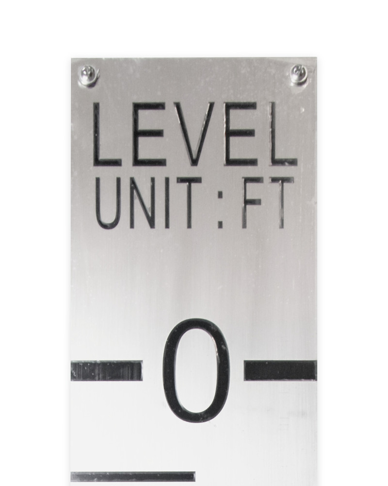
Scale plate, feet and inches (F) - Vapour seal VS
U-seal pot filled with silicone oil, in carbon steel and aluminum or in stainless steel, with a 1½ in union and nipple. For toxic or odorous vapours.
- Float guide pipe
Protects the float at fill inlets and in turbulence. Supplied by others, or on request.
Ordering code
- PL-100
- Scale
- Range
- Material
- Thread
- Option
| Position | Code | Description |
|---|---|---|
| Model | PL-100 | Plumbline™ float-and-board tank level gauge |
| Scale | F · M | Feet and inches · metric |
| Range | in or mm | Measuring range, per order, up to 49 ft (15 m) |
| Material | 4 | 304 SS |
| Thread | – | Confirmed at quotation |
| Option | VS | Vapour seal (optional) |
Specific gravity, fluid, temperature and tank height are stated on the order datasheet, not in the model code. The float is sized at the factory to suit the specific gravity.
Data
Technical specifications
Ratings
| Service | Atmospheric: fixed-roof, vented storage tanks |
|---|---|
| Fluid temperature | To 302 °F (150 °C) |
| Ambient temperature | −4 to +176 °F (−20 to +80 °C) |
| Installation | Suitable for outdoor installation |
| Measuring range | Per order, up to 49 ft (15 m); about 18 to 20 in (450 to 500 mm) less than the tank height |
| Specific gravity | Float and counterweight set for the specified SG; state the SG on the order |
Indication
| Reading | Target window with arrow pointers on a vertical scale board; scale numbered from the top down |
|---|---|
| Graduation | 2 in (50 mm) |
| Scale | Feet and inches, numbered every foot, or metric, numbered every 0.5 m; black marking on 304 SS plates |
Connections
| Top anchors | Two, 1 in male |
|---|---|
| Measuring wire | One 1½ in roof socket |
| Sheave elbows | 1½ in female, 304 SS |
| Vapour seal | 1½ in union and nipple |
| Thread standard | Confirmed at quotation |
Installation and maintenance
| Tank | Empty for installation: the bottom anchor is fixed to the tank floor |
|---|---|
| Float position | Away from fill inlets, or fit a float guide pipe |
| Roof pipe | Straight within ±0.2 in (±5 mm) |
| Brackets and supports | Cut to suit on site |
| Maintenance | Annual check; clean the float in viscous service |
Documentation
| Specification sheet | Technical specification sheet PL-TS-009 |
|---|---|
| Approval drawing | Issued after the purchase order |
- Ratings. Pressure and temperature ratings depend on materials, connections and configuration, and are confirmed at quotation.
- Water service. Where the water in the tank can freeze, consult Lamont Controls Engineering.
Drawings on this page
Applications
Selected projects
Enquiry
What to send for a quotation
A complete request is quoted fastest. Send the available details; Lamont Controls Engineering will ask for the rest.
- Tank height and diameterThe measuring range is set from the tank height: about 18 to 20 in (450 to 500 mm) less, up to 49 ft (15 m).
- Fixed roofPlumbline™ is for fixed-roof tanks only. State the roof type and include a drawing or photo where available.
- Fluid and specific gravityThe float and counterweight are set for the stated SG.
- Fluid temperatureTo 302 °F (150 °C).
- Scale units and vapour sealFeet and inches or metric; a vapour seal for toxic or odorous vapours.
- Quantity and required dateOne request can cover several tanks; give each a tag number.
Quotation
Request a quotation
Complete the fields below, or attach a tank drawing. Fields marked * are required. Process data speeds up the quotation. State the specific gravity: the float and counterweight are set for it.
For a general enquiry, select Quick message and provide your contact details with a brief note.
What happens nextLamont Controls Engineering reviews the request and replies within 1 to 3 business days with a quotation. The approval drawing is issued after the purchase order.
1-833-7LAMONT info@lamontcontrols.comQuestions
Float-and-board gauge questions
What is a float and board level gauge?
A float and board level gauge is a mechanical tank level indicator, also called a target level indicator or gauge board. A float on the liquid in the tank is linked by a wire over the roof to a target that travels on a scale board on the outside of the tank wall. The level is read directly, with no power and no glass.
Why does the scale read from the top down?
The target moves opposite to the float. As the level rises, the float rises and the target descends, so the target is at the top of the board when the tank is empty and at the bottom when it is full. The scale is numbered from the top down to match.
Which tanks is Plumbline™ suited to?
Fixed-roof, vented atmospheric storage tanks with fluid temperatures to 302 °F (150 °C), in services such as water and wastewater, fire and process water, crude and refined oils, fuels, glycols and vegetable oils. It is not for floating-roof or pressurized tanks.
What is the maximum measuring range?
Up to 49 ft (15 m). The measuring range is set from the tank height on the order: about 18 to 20 in (450 to 500 mm) less than the tank height.
Can Plumbline™ send a level signal to a control system?
No. Plumbline™ is a mechanical gauge for a local reading, with no power and no output signal. Where the control system needs a signal, use a level transmitter, or a Lamont magnetic level gauge with a LevelSync™ transmitter.
What does installation involve?
Three sockets on the roof, two 1 in for the top anchors and one 1½ in for the measuring wire, with 1½ in roof pipe between the two sheave elbows. The bottom anchor is fixed to the tank floor, so the tank must be empty. The roof penetrations, pipe and anchor fixing are by others, and the brackets are cut to suit on site.
Which option suits toxic or odorous vapours?
The vapour seal (VS): a U-seal pot filled with silicone oil, in carbon steel and aluminum or in stainless steel, with a 1½ in union and nipple.
What is the scale graduation?
Graduations every 2 in (50 mm). Feet-and-inch scales are numbered every foot, and metric scales every 0.5 m.
Downloads
Documentation
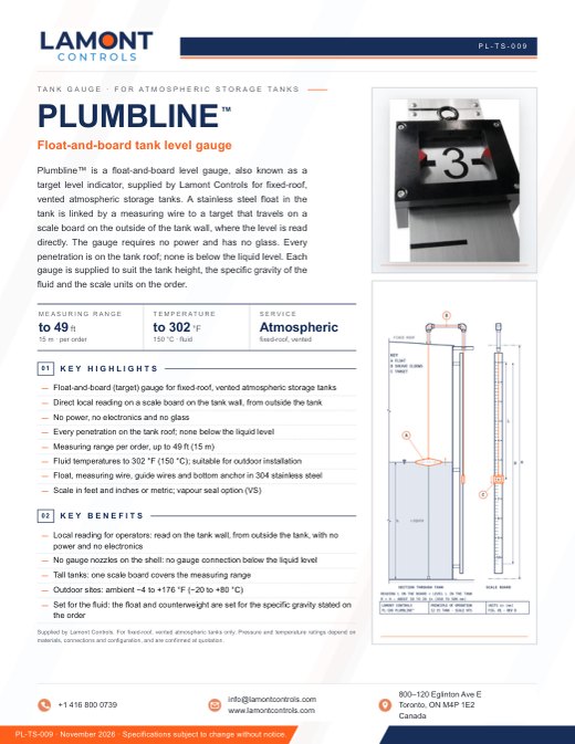 PL-TS-009 · NOVEMBER 2026Technical specification sheetDownload
In this sheet
- Page 1. Overview, key figures, highlights and benefits.
- Page 2. Technical specifications: principle, service, temperatures, measuring range, indication, construction and materials, parts supplied by others, installation, options and ordering code.
Drawings. Sales drawings are sent on request, after review. The approval drawing is issued after the purchase order.