Lamont Controls 1-833-7LAMONT Request a quotation Call

Cookies on this site

Analytics, advertising measurement and session recording stay off unless accepted. They show how the site is used and which advertising brings enquiries. The choice can be changed at any time under Cookie settings at the foot of each page. Privacy policy

How a magnetic level gauge works Principle of operation

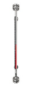
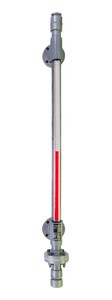
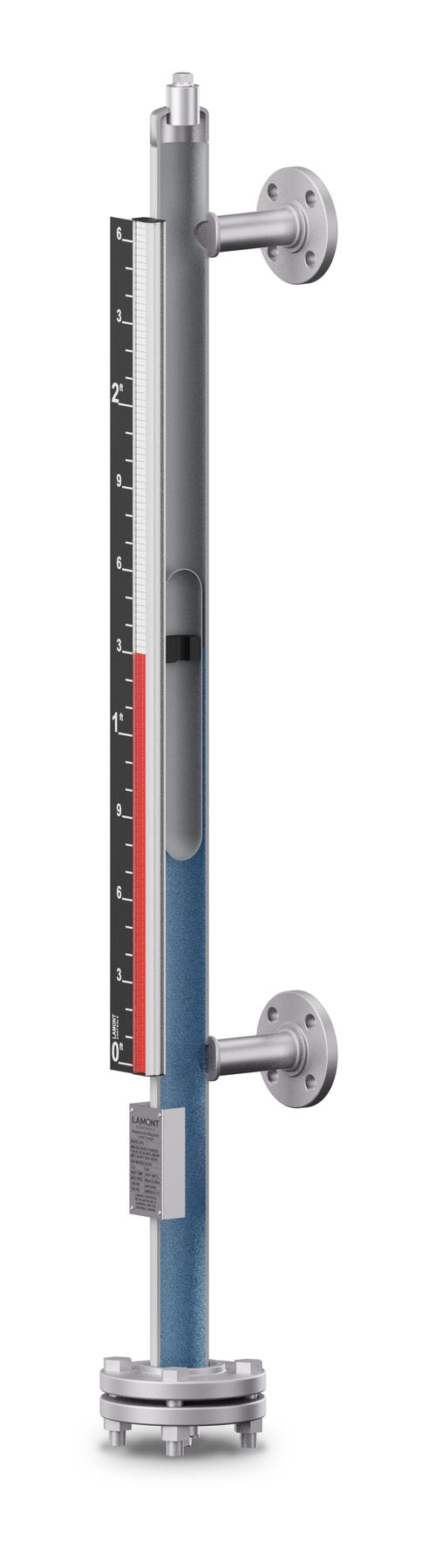
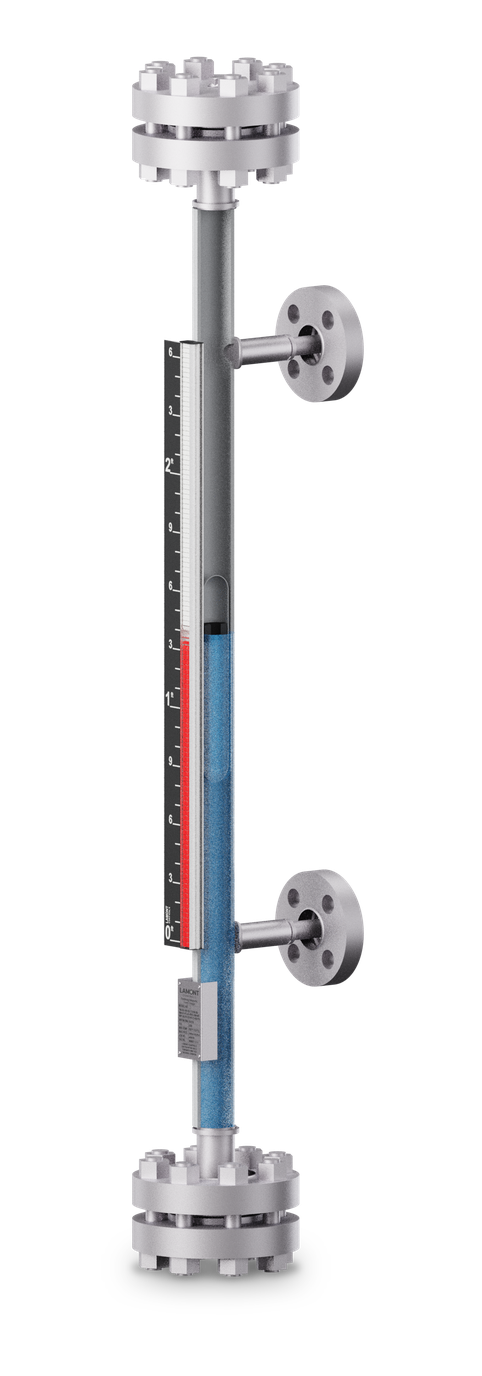
Cutaway render of a Magnamont gauge: half-section of the chamber with the MagnaLine float and its magnet at the liquid surface, and the ClearView indicator beside it
Cutaway · render, 30 in (762 mm) centre-to-centre; follows the level by percent of rangeAnimation · side–side, 48 in (1,219 mm) centre-to-centre; isolation valves not shown

A magnetic level gauge shows the level of a liquid in a vessel without glass and without power. A sealed chamber is joined to the vessel at two process connections, so the liquid in the chamber stands at the same level as the liquid in the vessel. A float carrying a permanent magnet rides that level. Outside the chamber, a column of indicator flags turns as the magnet passes: red below the level, white above it.

The indicator, and any transmitter or switches, mount outside the chamber; only the chamber and float are wetted. The reading holds through a power outage, and the same float drives LevelSync™ transmitters and SurePoint™ switches.

Typical accuracy
±0.4 in±10 mm, per application
Minimum SG
0.34Magnamont™, Fortimag™
Power to read
Nonemagnetic coupling
Configurations
5side–side to top-mount

Principle

Magnetic level gauge principle of operation

  1. Vessel

    The gauge is joined to the vessel at two process connections: one below the lowest level to be read, one above the highest.

  2. Chamber

    Chamber and vessel form communicating vessels. With the same pressure on both liquid surfaces, the liquid in the chamber stands at the vessel's level.

  3. Float

    A sealed MagnaLine™ float, weighted for the liquid's specific gravity, floats at the surface inside the chamber.

  4. Magnet

    The float carries a permanent magnetic assembly at the liquid surface. Its field passes through the chamber wall to the indicator.

  5. Flags

    Each flag in the ClearView™ indicator turns as the field passes: red below the level, white above. The level is read on the scale where the colours meet.

The communicating-vessel principle

The chamber is a vertical pipe joined to the vessel at two points: one connection below the lowest level to be read, one above the highest. Chamber and vessel form communicating vessels. Liquid enters and leaves the chamber through the bottom connection, and the vapour space above the liquid equalizes through the top connection.

With the same pressure on both liquid surfaces and the same liquid at the same temperature on both sides, the liquid in the chamber stands at the same height as the liquid in the vessel. As the vessel fills or drains, the chamber level follows it.

The level is read between the two connections. The distance between their centrelines is the gauge's centre-to-centre (C-C) dimension, the first figure on every order. A level below the bottom connection or above the top one is not measured, so the connections are placed to cover the full range the operator needs to see.

A vent at the top of the chamber and a drain at the bottom let the chamber be filled, flushed and emptied.

Bottom connection
Liquid. Fills and drains the chamber with the vessel.
Top connection
Vapour. Keeps the pressure above the liquid the same in the chamber as in the vessel.
Centre-to-centre (C-C)
The span between the two connection centrelines: the range the gauge reads.
Vent and drain
At the top and bottom of the chamber, for filling, flushing and emptying.

Float

The float and its magnet

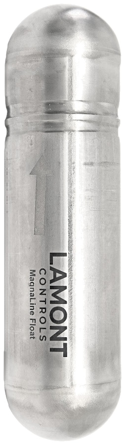
MagnaLine titanium float standing upright, magnet end at the top, etched with an upward arrow and the Lamont Controls mark
MagnaLine™ titanium float

The MagnaLine™ float is sealed and carries a permanent magnetic assembly. It is the part that follows the liquid: its magnet sits at the liquid surface and moves with it inside the chamber.

A float floats when it weighs less than the liquid it displaces, so the float's own specific gravity (SG) must be lower than the liquid's. Each float is weighted to the SG of the process liquid at operating temperature, and to the operating pressure, so that the magnet rides at the surface. A float weighted for the wrong SG sits too high or too low, and the reading is off by the difference.

Float selection starts from three figures: the liquid's SG at operating temperature, the temperature range, and the design pressure the float must withstand. A thicker float wall resists pressure but adds weight; a light liquid needs a light float that is still strong enough for the pressure. That is why the lowest SGs at high pressure call for engineered floats. The SG goes into the model code, so the float is built to it.

  • Magnamont™ and Fortimag™: liquids down to SG 0.34. Titanium floats are standard, 316 stainless steel is optional, and engineered floats (ball-segment, syntactic foam, exotic alloys, coated and lined) are available. On Magnamont, consult the factory below SG 0.45.
  • Polysight™: liquids down to SG 0.59, with PTFE, PVDF or polypropylene floats matched to the chamber and the chemistry.
  • Two-phase and solids-bearing service is reviewed by the factory.
Section B–B: plan through the float magnet Plan section at the liquid level: the magnet ring inside the float, the chamber wall around it, and the indicator outside the chamber with one flag wafer. The field of the magnet ring reaches the magnet in the flag wafer through the chamber wall. Flag waferwith its own magnetIndicatorMagnet ringFloatLiquidChamber wall316 SS
Section B–BPlan through the float magnet

Indicator

The flags and the scale

Flag detail · animation
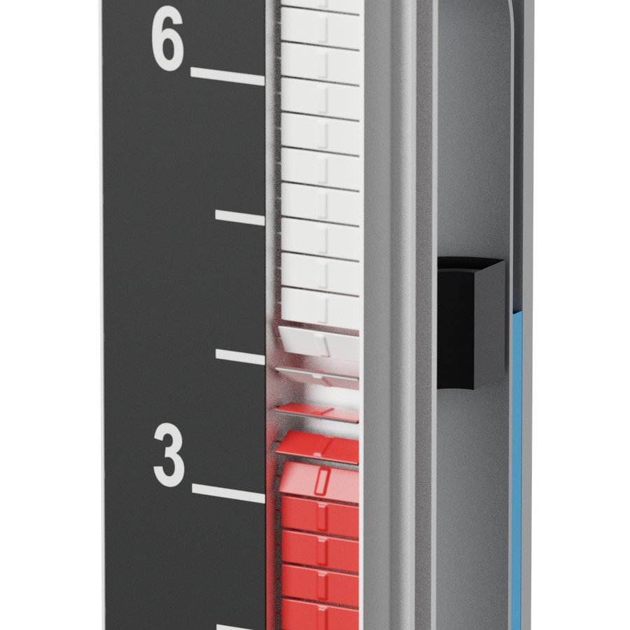
Render at the liquid level: the magnet ring inside the chamber, and the flags turning beside the scale, white above and red below
At the liquid level · render: the magnet ring inside the chamber, flags turning beside the scale
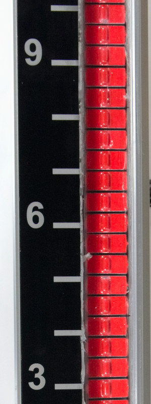
ClearView ISFS-300 indicator: red flags beside a black etched aluminum scale
ClearView™ ISFS-300 indicator

Flags. The ClearView™ indicator is a column of small flags in a housing clamped to the outside of the chamber. Each flag is a wafer with its own small magnet, pivoting on its axis. As the float's magnet passes, its field turns the flag over: white to red as the level rises, red to white as it falls. A flag stays as it was turned until the float passes it again, so the column holds the reading.

Why it reads with no power. Nothing in the local reading is electrical. The float's field reaches the flags through the chamber wall, and the float itself turns them. The reading holds through a power or control-system outage. The indicator, and any transmitter or switches, mount outside the chamber; only the chamber and float are wetted. A strong external magnet or a mechanical impact can turn a flag out of step; the float resets it the next time it passes. Other causes and remedies are in troubleshooting common issues with magnetic level gauges.

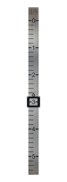
Scale. Where a scale is fitted, it runs beside the flags: etched aluminum, graduated in feet and inches, metres and centimetres, percent, or volume in gallons or litres to the tank. The standard Polysight™ indicator, IPVC-80, is supplied without a scale.

Indicator builds. Stainless flags in an aluminum housing are standard on Magnamont™ and Fortimag™, with high-temperature aluminum flags and a hermetically sealed, argon-filled indicator as options. Polysight uses PVC flags in a transparent PVC housing as standard. Each indicator is rated for where it sits, outside the chamber, and is matched to the service when the gauge is specified.

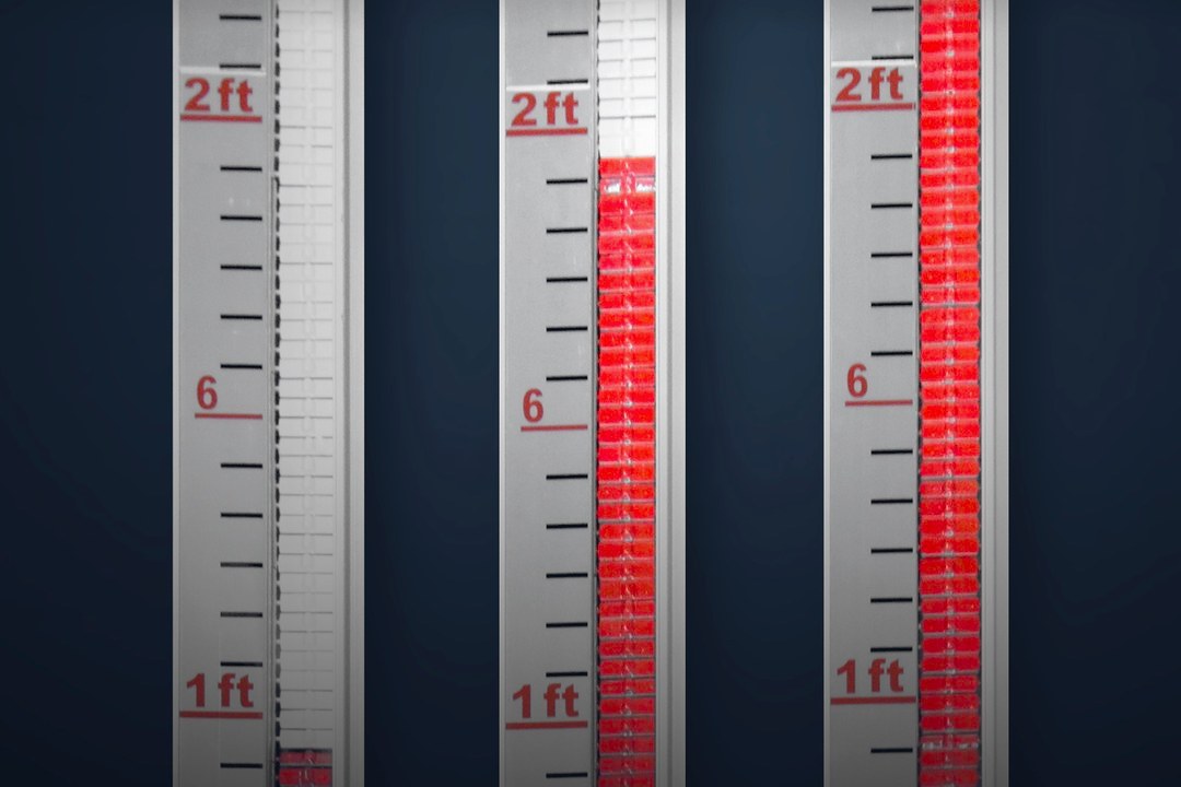
Three Magnamont indicators side by side at a low, a middle and a high liquid level: red flags below each level, white flags above, beside an etched scale in feet
Three levels, one principle. Magnamont™ indicators at a low, a middle and a high level: red below the liquid level, white above.

Gauge families

Magnamont, Fortimag and Polysight compared

All three magnetic level gauges work on the same principle. The chamber the field passes through, the float that rides the level and the indicator that shows it change with the service.

Magnamont, Fortimag and Polysight compared
SpecificationMagnamont™Fortimag™Polysight™
ChamberWelded 316 stainless steel; other alloys on request316 stainless steel, double-flanged top and bottom with weld-neck flangesCPVC (standard) or PVDF thermoplastic
PressureFull vacuum to 3,400 psig (234 bar)Full vacuum to 5,000 psig (345 bar)Full vacuum to 150 psig (10 bar)
Temperature−40 to +842 °F (−40 to +450 °C)−40 to +842 °F (−40 to +450 °C)−4 to +248 °F (−20 to +120 °C)
FloatMagnaLine™ titanium (standard); engineered floats on requestMagnaLine™ titanium (standard); ball-segment floats for the highest pressure classesMagnaLine™ PTFE, PVDF or polypropylene
Minimum SG0.34; consult factory below 0.450.340.59
Standard indicatorClearView™ ISFS-300: stainless flags, aluminum housingClearView™ ISFS-300: stainless flags, aluminum housingClearView™ IPVC-80: PVC flags, transparent PVC housing
AccuracyTypical ±0.4 in (±10 mm)Typical ±0.4 in (±10 mm)Typical ±0.4 in (±10 mm)

Pressure and temperature ratings depend on materials, connections and configuration, and are confirmed at quotation. Magnamont and Fortimag: lower temperatures on application review.

  • Chamber wall. The float's field reaches the flags through the chamber wall: 316 stainless steel on Magnamont and Fortimag, CPVC or PVDF on Polysight.
  • Float. A light liquid needs a light float, and high pressure needs a stronger float wall. Magnamont and Fortimag read liquids down to SG 0.34; Polysight, with thermoplastic floats, down to SG 0.59.
  • Float travel. An internal stop spring at the bottom of the Magnamont chamber, and dual internal stop springs in the Fortimag chamber, limit the travel of the float.
  • Indicator. Stainless flags in an aluminum housing on Magnamont and Fortimag; PVC flags in a transparent PVC housing on Polysight.
Cutaway render of a Fortimag gauge: half-section of the chamber between weld-neck double-flanged ends, with the float and the indicator
Fortimag™ Render · half-section between the double-flanged ends

Automation

Transmitters and switches on the same chamber

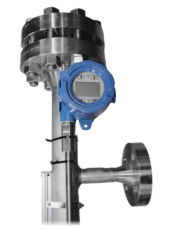
Externally mounted devices are magnetically coupled to the same float magnet as the flags. They have no wetted parts, need no additional vessel nozzle, and are fitted at the factory or in the field.

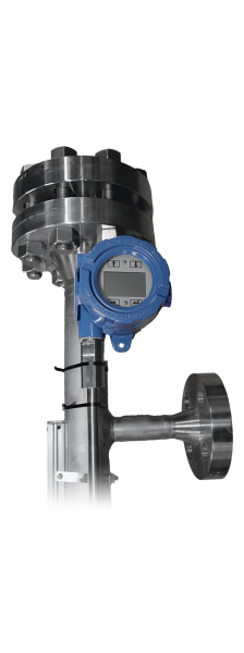
LevelSync magnetostrictive level transmitter with its display head and sensor rod

LevelSync™

Magnetostrictive level transmitter

A sensor tube along the chamber finds the float's magnet by magnetostrictive time-of-flight sensing and gives a continuous level signal. No moving parts and no routine recalibration.

Output
4–20 mA with HART®; Modbus RTU or DDA optional
Inherent accuracy
±0.039 in (±1 mm)
Order
Option MLT in the gauge model code
LevelSync™ transmitters
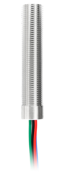
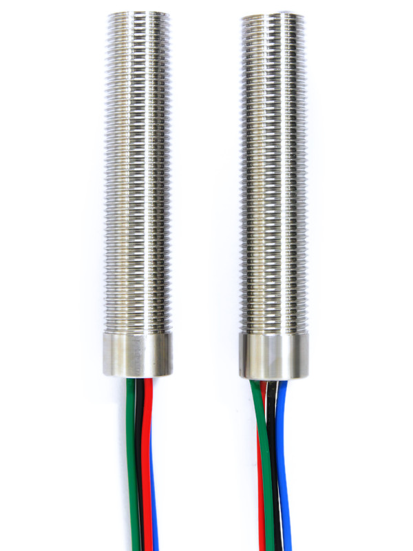
Two SurePoint magnetically actuated level switches with colour-coded leads

SurePoint™

Magnetic point-level switch

Each switch changes state as the float's magnet passes its set point, for high and low level alarms and basic control. No moving levers and no actuation power.

Contact
SPDT, latching
Per gauge
1 to 8 switches, options PLS-1 to PLS-8
Set point
Band clamp, adjustable along the chamber
SurePoint™ switches

FloatSense™ float-integrity monitoring (option FS) is available on Magnamont™, Fortimag™ and Polysight™. Hazardous-area certifications are held by Lamont's component manufacturing partner and apply to the supplied product. Final certification, temperature class and marking depend on configuration and are confirmed at quotation.

Accuracy

Accuracy and what affects it

Typical accuracy is ±0.4 in (±10 mm), subject to float design and application conditions. Three effects move the reading in operation. Each is handled when the gauge is specified, from the process data on the request.

Temperature and density

Most liquids get lighter as they warm. A float weighted for the liquid's SG at 60 °F (16 °C) sits deeper in the same liquid when it is hot, and reads low. Water is the familiar case: from standard steam tables, its SG is about 1.00 at 60 °F (16 °C), 0.96 at 212 °F (100 °C) and 0.89 at 350 °F (177 °C).

Give the SG at normal operating temperature and the range it moves through. The float is weighted for the condition that matters most, such as a high-level alarm or a fill limit.

Cool-chamber offset

The chamber and the vessel balance by pressure at the bottom connection, not by height. If the liquid in the chamber is cooler than in the vessel, it is denser, a shorter column of it balances the vessel, and the gauge reads below the true level.

An insulation blanket (option IB) with a clear window over the indicator keeps the chamber near vessel temperature. Heat tracing (option HT) adds freeze protection outdoors.

Interface service

For an interface between two liquids, such as oil over water, the float is weighted to sink through the upper liquid and float on the lower one, so the indicator shows the boundary between them. Give both SGs at operating temperature (option INT).

The larger the SG difference, the cleaner the reading. A small difference, or an emulsion layer between the liquids, is reviewed by the factory.

Cool-chamber offset, worked example A vessel holding water at 227 °F (108 °C), 59.4 lb/ft³ (952 kg/m³), with its level 48 in above the bottom connection, and an uninsulated gauge chamber at 150 °F (66 °C), 61.2 lb/ft³ (980 kg/m³). The cooler, denser water in the chamber stands about 1 3/8 in (36 mm) lower. Levels drawn to scale; widths not to scale. reads about1⅜ in(36 mm) low 48 in (1,219 mm) Vessel 227 °F (108 °C) 59.4 lb/ft³(952 kg/m³) Chamber,uninsulated 150 °F (66 °C)61.2 lb/ft³(980 kg/m³) Bottom connection: same pressure
Cool-chamber offset: worked exampleVessel water at 227 °F (108 °C), 59.4 lb/ft³ (952 kg/m³); an uninsulated chamber at 150 °F (66 °C), 61.2 lb/ft³ (980 kg/m³); true level 48 in (1,219 mm) above the bottom connection. The chamber column stands at about 48 × 59.4 ÷ 61.2 ≈ 46.6 in, so the gauge reads about 1⅜ in (36 mm) low.The float, weighted for hot water, rides slightly higher in the cooler liquid, which offsets only a small part of the error. Estimate; levels drawn to scale, widths not to scale.

Configurations

Process connection configurations

Renders · Magnamont™ shown · dimensions per application

The configuration names where the process connections sit on the chamber. Four use two connections, one in the liquid and one in the vapour space; top-mount sits on a single flanged connection on the vessel top.

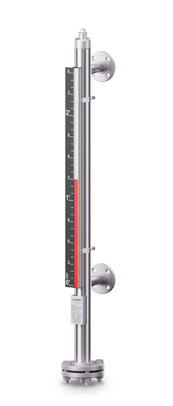
Render of a Magnamont gauge, side–side configuration: two flanged side process connections, vent at the top, drain at the bottom, indicator alongside
Side–sideStandard. Process connections on the side of the chamber, top and bottom.
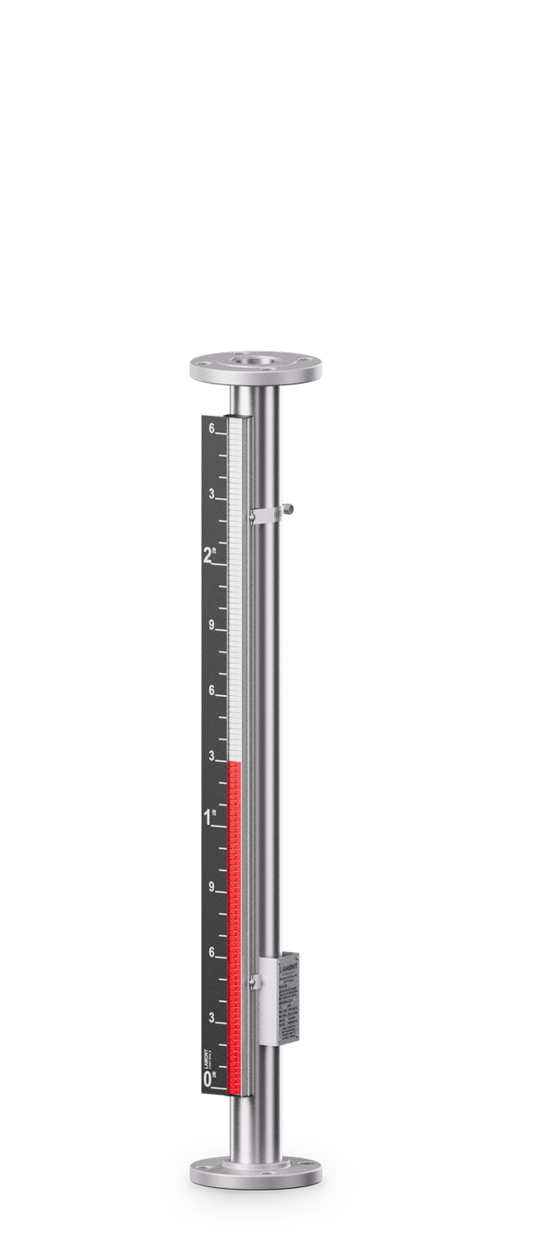
Render of a Magnamont gauge, top–bottom configuration: flanged process connections at the top and bottom ends, indicator alongside
Top–bottomFlanged process connections on the top and bottom ends of the chamber.
Render of a Magnamont gauge, top–side configuration: a flanged connection at the top end and a flanged side connection at the bottom, indicator alongside
Top–sideOne process connection on the top end, one on the side at the bottom.
Render of a Magnamont gauge, bottom–side configuration: a flanged side connection at the top and a flanged connection at the bottom end, indicator alongside
Bottom–sideOne process connection on the bottom end, one on the side at the top.
Render of a Magnamont gauge, top-mount configuration: a single flanged process connection at the bottom for mounting on the vessel top, indicator alongside
Top-mountChamber and indicator on a single flanged connection on the vessel top.

Custom dual-chamber arrangements are available on Magnamont and Fortimag™ (option X).

Quotation

What to send for a quotation

Lamont Controls Engineering selects the float, the chamber and the indicator from the process data. A complete request includes:

  • Fluid and its specific gravity at operating temperature; for interface service, both liquids and both SGs
  • Operating and design pressure
  • Operating and design temperature
  • Centre-to-centre (C-C) distance between the process connections
  • Process connections: size and rating, and the configuration: side–side, top–bottom, top–side, bottom–side or top-mount
  • Options: LevelSync™ transmitter, SurePoint™ switches, insulation blanket or heat tracing, and the scale units
  • Quantity and the required date
  • For a replacement: the model code on the installed gauge's nameplate

A process datasheet can be sent in place of this list.

How to specify a magnetic level gauge

Questions

Frequently asked questions

How does a magnetic level gauge work?

The chamber is joined to the vessel at two points, so the liquid in it stands at the same level as the liquid in the vessel. A float carrying a permanent magnet rides that level, and its field turns the indicator flags outside the chamber: red below the level, white above it.

Does a magnetic level gauge need power?

Not for the local reading. The flags are turned by the float's magnet. A LevelSync™ transmitter, if fitted, is loop powered.

Is a magnetic level indicator the same as a magnetic level gauge?

Yes. Magnetic level indicator, MLI, mag gauge, bypass level indicator and magnetic float level gauge all name the same design: a float with a magnet in a chamber, driving an indicator outside it.

Which specific gravity is specified for the float?

The liquid's SG at normal operating temperature, plus the range it moves through. For an interface between two liquids, give both SGs.

Can a magnetic level gauge measure an interface between two liquids?

Yes. The float is weighted to sink through the upper liquid and float on the lower one, so the indicator shows the boundary. Give both SGs at operating temperature.

Why does a gauge on a hot tank read low?

Two common reasons: the float is weighted for cold liquid, or the chamber is cooler than the vessel and holds denser liquid. Weighting the float for the hot SG and insulating the chamber correct most cases.

How accurate is a magnetic level gauge?

Typical accuracy is ±0.4 in (±10 mm), subject to float design and application conditions. A LevelSync™ transmitter on the same chamber has an inherent accuracy of ±0.039 in (±1 mm).

Can a transmitter or switches be added later?

Yes. LevelSync™ transmitters and SurePoint™ switches are externally mounted and magnetically coupled to the same float. They have no wetted parts, need no additional vessel nozzle, and are fitted at the factory or in the field.

Request a quotation Call