
Scope
A magnetic level gauge is engineered to order, so a quotation starts from the process data. This guide covers three steps: the data a quotation needs, the choice of gauge, and the Lamont model code. It is written for the engineer who prepares a magnetic level gauge datasheet or a request for quotation.
A request does not need a model code. Process data is enough; Lamont Controls Engineering recommends the gauge and verifies the model code at quotation.
Specification checklist
The checklist follows the Lamont quotation form and the paper quote request form, LC-QR-010. Items that are not known may be left blank; Lamont Controls Engineering follows up as needed.
Process data
- Fluid. Name the liquid; for interface service, both liquids.
- Specific gravity. At operating temperature, to two decimals; for interface service, of both liquids.
- Pressure. Operating and design.
- Temperature. Operating and design.
- Hazardous area classification. Where one applies.
Gauge and options
- Centre-to-centre dimension. The distance between the process connections, in inches or millimetres.
- Process connections. Type (flanged, threaded or welded), size and rating; for flanges, the class and the facing.
- Chamber configuration. Side–side, top–bottom, top–side, bottom–side or top-mount.
- Materials. Chamber and float materials, and any material compatibility requirement.
- Construction code. ASME B31.1, ASME B31.3 or industrial grade.
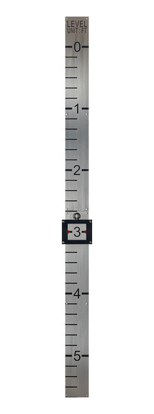
- Indicator and scale. The indicator, and the scale units: feet and inches, metric, percent, gallons or litres.
- Vent and drain. Type and size of each, or none.
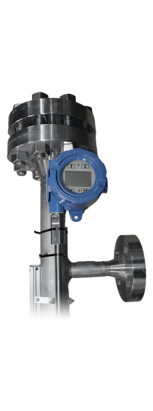
- Transmitter and switches. Whether a level transmitter is required; for level switches, the quantity and the switch positions.
- Insulation and heat tracing. Whether an insulation blanket or heat tracing is required.
Quantity, tags and drawings
- Quantity and tag numbers. For several gauges, list each tag in one request.
- Required date. The date the gauges are needed.
- Sketch or vessel drawing. Show the tank, the connection locations, the switch positions and the elevations. A datasheet, a drawing or a P&ID can be attached to the form.
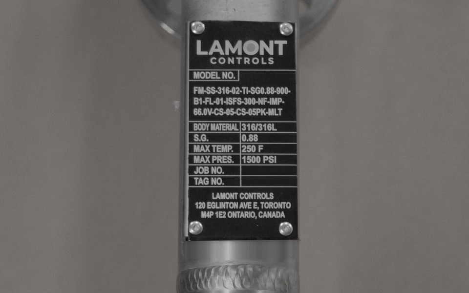
- Replacement gauges. Include a photo of the existing nameplate.
Choosing the gauge
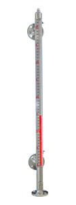
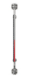
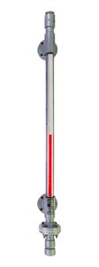
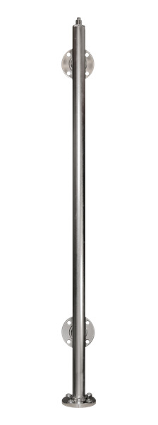
Lamont Controls builds Magnamont™, Fortimag™ and Polysight™ gauges, which differ in chamber material, construction, and pressure and temperature ratings. The magnetic level gauges page compares them in full. Position 01 of the model code names the gauge.
 Magnamont™ |  Fortimag™ |  Polysight™ | |
|---|---|---|---|
| Duty | SS316 gauge for industrial service | Extreme pressure and temperature; double-flanged chamber, weld-neck flanges, dual stop springs | CPVC or PVDF thermoplastic gauge for corrosive service |
| Pressure | Full vacuum to 3,400 psig (234 bar) | Full vacuum to 5,000 psig (345 bar) | Full vacuum to 150 psig (10 bar) |
| Temperature | −40 to +842 °F (−40 to +450 °C); lower temperatures on application review | −4 to +248 °F (−20 to +120 °C), material-dependent | |
| Minimum SG | 0.34 | 0.59 | |
| Process connections | Flanged, threaded (FNPT, MNPT) or welded (Weldolet, Sockolet); ½ to 4 in | Flanged, FNPT or MNPT; 1 in, 1½ in and 2 in; 3 in consult factory | |
| Standard centre-to-centre | To 222 in (5,640 mm); longer on request | ||
Pressure and temperature ratings depend on materials, connections and configuration, and are confirmed at quotation.
Reading the model code, position by position
The Lamont model code states the complete gauge in 18 positions, written in order and separated by hyphens. Positions 01 to 17 are always present. Position 18 holds the options and is left off when none is ordered. Magnamont and Fortimag share most codes; Polysight has its own for materials, indicators and finish.
Codes such as ISFS-300 and HS-300 are single field values; positions are delimited by field, not by every hyphen.
Chamber and float: positions 01 to 06
| Position | Magnamont and Fortimag | Polysight |
|---|---|---|
| 01 Product type | MM Magnamont™ · FM Fortimag™ · PS Polysight™ | |
| 02 Chamber configuration | SS side–side (standard) · TB top–bottom · TS top–side · BS bottom–side · TM top-mount | |
| 03 Chamber material | 316 SS316 (standard) · CC custom or exotic: Hastelloy, Monel K-500, Inconel 625, coated or lined; consult factory | CPVC (standard), to ~199 °F (~93 °C) · PVDF for aggressive or hot corrosive service, to ~248 °F (~120 °C) · CC custom; consult factory. Chamber limits are service-dependent. |
| 04 Chamber size | 15 1½ in · 02 2 in (standard) · SP special. Fortimag adds 25 2½ in, used for Class 1500; Class 2500 is built to order (SP). | 02 2 in (only) · SP special, custom only |
| 05 Float material | TI titanium (standard) · SS 316 stainless steel · CU custom: coated, lined and exotic floats; consult factory | PP polypropylene: SG ≥ 0.59, ≤ 176 °F (80 °C) · PV PVDF: SG ≥ 0.79, ≤ 212 °F (100 °C) · TF PTFE: SG ≥ 0.84, ≤ 248 °F (120 °C), low-pressure service; consult factory · CU custom; consult factory |
| 06 Float specific gravity | SGX.XX, user-specified, for example SG1.00. Minimum SG 0.34 for Magnamont and Fortimag, 0.59 for Polysight. Interface service adds the second liquid at position 18. | |
Pressure, construction and connections: positions 07 to 10
| Position | Magnamont and Fortimag | Polysight |
|---|---|---|
| 07 Pressure / flange class | ANSI 150 · 300 · 600 · 900 · 1500; Fortimag adds 2500. Special-order flanges: DIN PN10 · PN16 · PN25 · PN40; JIS J5K · J10K · J16K · J20K. SP special, including PN63 and PN100. | 150 ANSI 150 (standard) · PN10 DIN PN10 and J5K JIS 5K, on request |
| 08 Construction code | IG Industrial grade · B1 ASME B31.1 Power Piping · B3 ASME B31.3 Process Piping | IG Industrial grade, thermoplastic fabrication |
| 09 Process connection type | FL flanged · FNPT female NPT · MNPT male NPT · WO Weldolet · SO Sockolet · CS custom | FL flanged · FNPT female NPT · MNPT male NPT · CS custom |
| 10 Process connection size | ANSI / NPT: 05 ½ in · 075 ¾ in · 01 1 in · 125 1¼ in · 15 1½ in · 02 2 in · 25 2½ in · 03 3 in · 04 4 in. DIN: DN15 · DN20 · DN25 · DN32 · DN40 · DN50 · DN65. JIS: 15A · 20A · 25A · 32A · 40A · 50A. CS custom or special. | ANSI / NPT: 01 1 in · 15 1½ in · 02 2 in (standard) · 03 3 in, consult factory. On request: DIN DN25 · DN40 · DN50; JIS 25A · 40A · 50A. CS custom. |
Only sizes valid for the flange standard chosen at position 07 apply.
Indicator, scale and length: positions 11 to 14
| Position | Magnamont and Fortimag | Polysight |
|---|---|---|
| 11 Indicator (ClearView™) | ISFS-300 (standard) stainless steel flags, aluminum housing, with scale; 572 °F (300 °C). ISF-300 as above, no scale; 572 °F (300 °C). IAF-450 high-temperature aluminum flags, with scale; 842 °F (450 °C). HS-300 hermetically sealed, argon-filled, stainless housing with scale; 572 °F (300 °C). IX no indicator. | IPVC-80 (standard) PVC flags, transparent PVC housing; 176 °F (80 °C). IPVC-120 PVC flags, aluminum housing with scale; 248 °F (120 °C). ISFS-300 stainless steel flags, aluminum housing with scale; 572 °F (300 °C), Polysight limit 248 °F (120 °C). HS-80 hermetically sealed, argon-filled, condensation- and fog-proof; 176 °F (80 °C). IX no indicator. |
| 12 FloatSense™ | NF no FloatSense (standard) · FS FloatSense™ float-integrity monitoring | |
| 13 Scale | IMP feet and inches · MET metres and centimetres · PER percent, 0–100 % · GAL gallons and LIT litres, each custom-graduated to tank volume · NS no scale · CUS custom | |
| 14 Centre-to-centre length | XX.XV inches, for example 120.0V · XXXXE millimetres, for example 3048E. Standard lengths to 222 in (5,640 mm); longer lengths on request. | |
Temperatures at position 11 are ratings of the indicator, which is mounted outside the chamber. They are not process temperature limits of the gauge. On Polysight, PVC-housed indicators (IPVC-80) are recommended for corrosive-fume environments, and hermetically sealed (HS-80) for condensation, humidity or washdown.
Vent, drain, finish and options: positions 15 to 18
| Position | Magnamont and Fortimag | Polysight |
|---|---|---|
| 15 Vent, type and size | Type: M MNPT · F FNPT · FL flanged, ½ in and up · CS custom machined port · NV no vent. Size: 18 ⅛ in · 025 ¼ in · 38 ⅜ in · 05 ½ in · 75 ¾ in · 1 1 in · 00 none. Sizes below ½ in are threaded only. | Type: F FNPT (standard) · M MNPT · NV no vent. Size: 05 ½ in (standard) · 75 ¾ in · 1 1 in · 00 none. Flanged: consult factory. |
| 16 Drain, type and size | As position 15, with ND for no drain. Type and size are written together: F-05 is a ½ in FNPT port, NV-00 no vent, ND-00 no drain. | |
| 17 Finish | PA passivated (standard), full immersion per ASTM A380 / A967 · EP electropolished, external surfaces, per ASTM B912 · PT painted and PC powder coated, exterior and non-wetted | NT natural, as moulded (standard) · PT painted, on CPVC only, for outdoor and UV service; not available on PVDF |
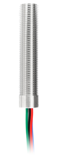
| 18 Options (stackable) | MLT LevelSync™ magnetostrictive level transmitter · PLS-1 to PLS-8 SurePoint™ clamp-on switches, quantity 1 to 8 · INTSGX.XX interface service, second liquid SG, for example INTSG0.85 · X custom options. Magnamont and Fortimag only: IB insulation blanket · HT heat tracing. Fortimag only: VG VaporGuard™ flashing-service float protection. | |
Worked example
The Magnamont model code reference, MM-MC-010, lists this sample configuration: ASME B31.1, Class 150, passivated.
MM-SS-316-02-TI-SG1.00-150-B1-FL-02-ISFS-300-NF-IMP-120.0V-F-05-F-05-PA
- 01MMMagnamont
- 02SSSide–side chamber configuration
- 03316SS316 chamber
- 04022 in chamber
- 05TITitanium float
- 06SG1.00Float for a specific gravity of 1.00
- 07150ANSI Class 150
- 08B1ASME B31.1 Power Piping
- 09FLFlanged process connections
- 10022 in process connections
- 11ISFS-300Stainless steel flags, aluminum housing, with scale
- 12NFNo FloatSense
- 13IMPScale in feet and inches
- 14120.0V120.0 in centre-to-centre
- 15F-05½ in FNPT vent
- 16F-05½ in FNPT drain
- 17PAPassivated
- 18noneNo options; the code ends at position 17
How the approval drawing confirms the specification
Lamont Controls Engineering verifies the model code at quotation, against the process data sent with it. The approval drawing is issued after the purchase order, and the design is confirmed on it before fabrication starts. Check the drawing against the vessel drawing and the datasheet before it is approved.
Sales drawings are requested through the drawing request form. Lamont Controls Engineering sends them after review.
Pressure tested before shipment; hydrostatic test at not less than 1.5 × design pressure where specified. Test reports available.
Common specification mistakes
- Operating conditions without design conditions. The ratings of the gauge must cover the design pressure and design temperature, not only the operating conditions.
- Maximum pressure and maximum temperature read together. They are separate limits and do not apply together.
- Specific gravity missing, or not at operating temperature. Each float is weighted to the fluid's specific gravity. On hot water service, a float weighted for cold water reads low.
- Flange class and connection size from different standards. DN sizes go with DIN classes and A sizes with JIS classes.
- Indicator rating read as a process limit. The temperature in an indicator code is the rating of the indicator, not of the gauge.
- Polysight temperature taken from the chamber alone. The maximum operating temperature is further limited by the float rating at position 05.
Request a quotation
Send the checklist data through the quotation form. The second link below opens the form with the model code of the worked example filled in. Spare parts for an existing Lamont gauge are ordered by the nameplate model code on the spare parts page.
Request a quotation Request a quotation with this model code
Frequently asked questions
What information is needed to quote a magnetic level gauge?
The fluid and its specific gravity, the operating and design pressure and temperature, the centre-to-centre dimension, the process connection size and rating, and the quantity. Tag numbers, a datasheet and a vessel drawing or sketch complete the request. A model code is not required.
What is the minimum specific gravity for a magnetic level gauge?
Magnamont and Fortimag gauges are specified for a specific gravity of 0.34 or higher. Polysight gauges are specified for 0.59 or higher. Both limits are subject to float design and application conditions.
How many positions does the Lamont model code have?
The Lamont model code has 18 positions. Positions 01 to 17 are always present. Position 18 holds options and is left off when no option is ordered. Codes such as ISFS-300 are single field values, so positions are counted by field and not by hyphen.
How is the centre-to-centre length written in the model code?
Position 14 states the centre-to-centre length. A length in inches ends in V, for example 120.0V. A length in millimetres ends in E, for example 3048E. Standard lengths run to 222 in (5,640 mm) centre-to-centre; longer lengths are available on request.
Which construction codes can be specified?
Position 08 states the construction code. Magnamont and Fortimag gauges are built to ASME B31.1 Power Piping (B1), ASME B31.3 Process Piping (B3) or industrial grade (IG). Polysight gauges are industrial grade, thermoplastic fabrication.
Can a transmitter and level switches be included in the model code?
Yes. Position 18 holds the options. MLT adds a LevelSync magnetostrictive level transmitter. PLS-1 to PLS-8 add one to eight SurePoint clamp-on switches. Options are stackable, so one code can carry both.
When is the approval drawing issued?
The approval drawing is issued after the purchase order. The design is confirmed on the approval drawing before fabrication starts.